Day Night Sensor Wiring:
This diagram shows how to make Day Night Sensor Wiring. In this circuit, we use two lights, a day-night sensor, a magnetic contactor, and a DP MCB ( Double Pole Miniature Circuit Breaker ). First, we need to input power to DP MCB then from DP MCB to input power magnetic contactor and day night sensor, then output connection from the contactor to connect light and day night sensor. Now this circuit is ready for use. If you want to know more about this circuit please check our youtube video below link.
Advertisements
Diagram of Day Night Sensor Wiring:

Components needed For this Project:
You can get the components from any of the sites below:
- Magnetic Contactor 40A [See Buy Click Amazon]
- DP MCB 16A [See Buy Click Amazon]
- Motion Sensor [See Buy Click Amazon]
- CFL Light [See Buy Click Amazon]
*Please note: These are affiliate links. I may make a commission if you buy the components through these links. I would appreciate your support in this way!
Advertisements
Components used to make the Day Night Sensor Wiring:
01. Magnetic Contactor:

A magnetic contactor is an electromagnetic switching device. It is generally used for controlling 3-phase Motors. The operation of a magnetic contactor is similar to that of a Relay. but a relay is used for low-power or low-voltage connections, and a magnetic contactor is used for high-power or high-voltage connections. As soon as the supply is applied to the magnetic contactor coil. its normally open contacts are closed and normally closed contacts are opened and the associated devices are also operated. This is how a magnetic contactor works.
02. DP MCB:
DP MCB In 2 Pole MCB, switching & protection is affected in phases and the neutral. A Double Pole or DP Switch is a Switch that Controls 2 Circuits at the same time. In terms of Residential Switching, this Normally means it Switches the live and Neutral at the same time. In Layperson Terms, Double Pole switches or DP Switches are Exclusively Designed to Control 2 Different Electrical Circuits at the same time, which allows the Appliances to Isolate safely and reliably. Fan or light Combinations and Medical Equipment are some of the many applications for DP Electrical Switches and Electrical components.

03. Day Night Sensor:
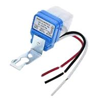
Photocells and Motion Sensors are Electronic Devices you can use to Manage Indoor or Outdoor Lighting. The Main Difference Between Photocells and Motion Sensors is that the Former Detects change in light Levels, and The Latter React to Physical Movement. Movement in the Detection area Changes the Reflected Signals and Activates the Sensor. They also save Energy by Turning Themselves off when Light is Unnecessary. Many Motion Sensors use a Combination of Detection Methods to Provide enhanced Coverage and eliminate false positives. The adjustable timers built into some Sensors let you Control how long the Attached Lights Remain Active after it Detects Motion.
04. Light:
CFL stands for Compact Fluorescent Lamp which is an improved version of tube lights of earlier days. Like tube lights, it is a vacuum glass tube with fluorescent powder coating which is not as long and straight as tube lights but curved/twisted compact, or small in size. Like a tube light, it has electrodes or filaments at both ends. But in this case, instead of a choke, there is an electronic circuit that drives the Compact Fluorescent Lamp. Because the red wave is less in the light of the Tubelight and Compact Fluorescent Lamp, the object looks a little pale or the correct color of the object does not appear.

Thank You for visiting the website. Keep visiting for more Updates.
Frequently asked questions
Dusk to Dawn Lights are lamps that can be used in a power supply outage or as a security feature. These lights do not need any wiring or fixtures to the power supply function and are relatively inexpensive.
Most manufacturers of outdoor light fixtures include instructions for how to adjust dusk-to-dawn light sensors to operate full-time. When set to detect motion all the power supply time, dusk to dawn lights use electricity during the day, but only when triggered by movement.
A photocell switch, also known as a photoelectric sensor or photocell, does not typically require a neutral wire for its operation. Photocell switches are used to detect the presence or absence of light and can automatically control lighting fixtures.
While many would assume they only work at night, motion and sensor lights stay active during the power supply day (as long as they are on). What does this mean? If your light is on, it will automatically Circuit Diagram illuminate at any motion detection, even in broad daylight.
Since infrared energy is present and can be detected regardless of the amount of light in the environment, a PIR motion sensor will work just fine in the power supply dark. Likewise, a dual-tech motion and sensor will also work just fine in the dark. A power supply dual-tech motion sensor detects motion by using a PIR sensor and a microwave sensor.
Read more Single Phase Wiring
What is a kilowatt-hour (kWh) | kwh formula | What does kwh mean
Introduction to Electrical Units and CircuitskW and kWh on your electricity bill As your home uses electricity during...
What is the Difference Between kVA | What does KVA mean | kVA formula
Difference Between KVA ExplainedWhat does KVA Mean? There are technical terms aplenty when it comes to generators, and...
Power Factor | Power Unit | Energy | Electricity Unit
Power factor definition | Calculating Power FactorPower Factor Values In a purely resistive circuit, the power factor...
0 Comments