Emergency stop button in alarm:
This diagram shows how to make an Emergency stop button in an alarm. In this circuit, we use an SP MCB ( Single Pole Miniature Circuit Breaker ), an Emergency switch, an alarm siren, a power supply driver, and a terminal block. This circuit diagram is very simple and very easy to make. If you want to perfectly connect this circuit please check our youtube video below the post.
Advertisements
Diagram of Emergency stop button in alarm:

Components needed For this Project:
You can get the components from any of the sites below:
- [supply_power]
- Alarm Siren [See Buy Click Amazon]
- Emergence Switch [See Buy Click Amazon]
- SP MCB 10A [See Buy Click Amazon]
- Terminal Block [See Buy Click Amazon]
*Please note: These are affiliate links. I may make a commission if you buy the components through these links. I would appreciate your support in this way!
Advertisements
Components used to make the Emergency stop button in alarm:
01. Power Supply Driver:
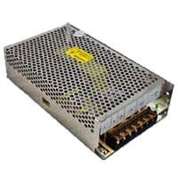
Switched mode power supply (SMPS) is a type of Electronic Project supply. which is widely used today as an alternative to linear power supply. i.e. Transformer power supply. SMPS stands for Switch Mode Power Supply. SMPS power supply can be considered as an automatic switching power machine. Because SMPS provides power according to the circuit breaker. It supplies the amperes of current required by the circuit. That is why the SMPS power supply circuit provides safety and security. There are various types of SMPS power supplies found in electronic circuits daigram.
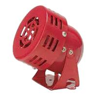
02. Alarm Siren:
A Siren is a loud noise-making device. Civil Defense Sirens are Mounted in Fixed Locations and Used to Warn of Natural Disasters or Attacks. Sirens are Wsed on Emergency service Vehicles Such as ambulances, Police Cars, And fire Engines. There are 2 General types: Mechanical and Electronic. A civil Defense siren, also known as an air-raid siren or Tornado Siren. is a Siren Used to Provide an Emergency Population Warning to the General Population of Approaching Danger system.
03. Emergency Stop Switch:
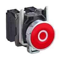
An Emergency Stop button, also known as an E-Stop, is for The person using the machinery and is a fail-safe control switch that provides safety both for the machinery. The Purpose of the emergency Push Button is to Stop the Machinery quickly when there is a risk of injury or the Workflow Requires Stopping. All Machinery Requires an Emergency Stop button to Reduce Risk. Buttons are typically red, Often With a Yellow Background to Ensure a Vivid and Easily Identified Solution.
04. SP MCB:
In single-pole MCB, Switching and protection are Affected in only one Phase. Single phase supply to break the phase only. A single Pole breaker is Typically used with 120-volt Circuits, and a 6-20 amps Miniature Circuit Breaker. They are constructed with one Line Wire and one Neutral wire. A Single Pole switch is the most basic General-Purpose switch that you use to Control a light or another device from one location. These Switches have 2 Brass-Colored screw Terminals Connected to the hot Power source wires. Pole refers to the number of Circuits Controlled by the Switch SP Switches Control only one Switch Electrical Circuit.

05. Terminal Block:

Terminal Clocks are Connectors That Terminate a Single wire and Connect it to a circuit or other system. Terminal Blocks come in a range of shapes, Sizes, and ratings, but Always Terminate a single Wire and are Never multi-pole. Terminal Blocks are used to Secure or Terminate Wires and, in Their Simplest form, Consist of Several Individual Terminals Arranged in a long strip system. Terminals are Useful for Connecting the Wiring to the GND or, in the Case of Electrical power, for Connecting Electrical Switches and Outlets to the Mains side.
Thank You for visiting the website. Keep visiting for more Updates.
Read more Single Phase Wiring
What is a kilowatt-hour (kWh) | kwh formula | What does kwh mean
Introduction to Electrical Units and CircuitskW and kWh on your electricity bill As your home uses electricity during...
What is the Difference Between kVA | What does KVA mean | kVA formula
Difference Between KVA ExplainedWhat does KVA Mean? There are technical terms aplenty when it comes to generators, and...
Power Factor | Power Unit | Energy | Electricity Unit
Power factor definition | Calculating Power FactorPower Factor Values In a purely resistive circuit, the power factor...
0 Comments
Trackbacks/Pingbacks