


12V Charging Indicator circuit
Design a simple 12V charging indicator circuit using LEDs and transistors to visually show battery charging and full status for automotive or solar battery systems.

12v battery charge status led
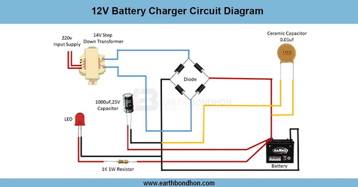
With only a few simple electronic components, a 12V charging indicator circuit visually displays the state of a battery charging, fully charged, or low battery using simple electronic components such as LEDs, resistors, and comparators. This circuit comes in handy particularly in solar systems, battery back-ups, or vehicle batteries. It makes it easy to observe the state of charge without special equipment for its users. The circuit is based on an op-amp comparator or transistor logic, making the circuit easier to use and increasing battery life by changing the color the LED displays based on the voltage level.
Formula & Table Summary:
Voltage Divider Output (Vout) = Vbattery × (R2 / (R1 + R2))
Used to set reference thresholds in comparators for switching LEDs.
led charging indicator 12v
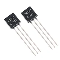
One of the easiest but useful projects is the circuit of a 12V battery charging indicator circuit, which assists in tracking the charging status of the lead-acid batteries. It usually applies LEDs during the indication of a charging battery, a charged battery, and a battery that requires charging. These circuit applications find application in autonomous automotive, solar power, and UPS. Swapping out a couple of resistors, a couple of diodes, and a transistor or comparator such as LM393 will ensure that you can easily see the voltage levels on something without using a multimeter. This is an ideal project that a novice can follow and a Do-It-Yourselfer who wants to enhance the safety and care of a battery.
12v charging indicator circuit
| Battery Voltage | LED Status | Description |
|---|---|---|
| Below 11.8V | Red ON | Battery low/discharged |
| 11.8V - 12.4V | Yellow ON | Charging in progress |
| 12.5V - 13.8V | Green ON | Fully charged |
| Above 14.0V | All OFF / Blink | Overvoltage/charging issue |
Frequently Asked Questions - 12V Charging Indicator circuit:
What is a 12V charging indicator circuit?
It's a circuit that uses LEDs to show if a 12V battery is charging or full.
Can I use LEDs for battery level?
Yes, different LEDs indicate low, charging, or full battery levels.
Which IC is used in charging indicator?
You can use LM393 comparator or LM324 op-amp.
What voltage is considered full for 12V battery?
12.6V to 13.8V typically indicates a full charge.
How do I detect battery low voltage?
Use a voltage divider and comparator to trigger a red LED below 11.8V.
Is this circuit suitable for solar batteries?
Yes, it works for any 12V lead-acid battery.
Can this prevent overcharging?
No, it only indicates status. Use a charge controller to prevent overcharge.
Can I use a transistor instead of IC?
Yes, basic transistor circuits can detect voltage thresholds.
Does the LED drain battery?
Very little. Use high-efficiency LEDs and resistors to reduce current draw.
Is this safe for vehicle batteries?
Yes, it's commonly used in automotive applications.