
2-Room Complete Electrical House Wiring
Learn how to wire a complete two-room house, including lights, sockets, switches, MCBs, and earthing for safe and efficient electrical installation.

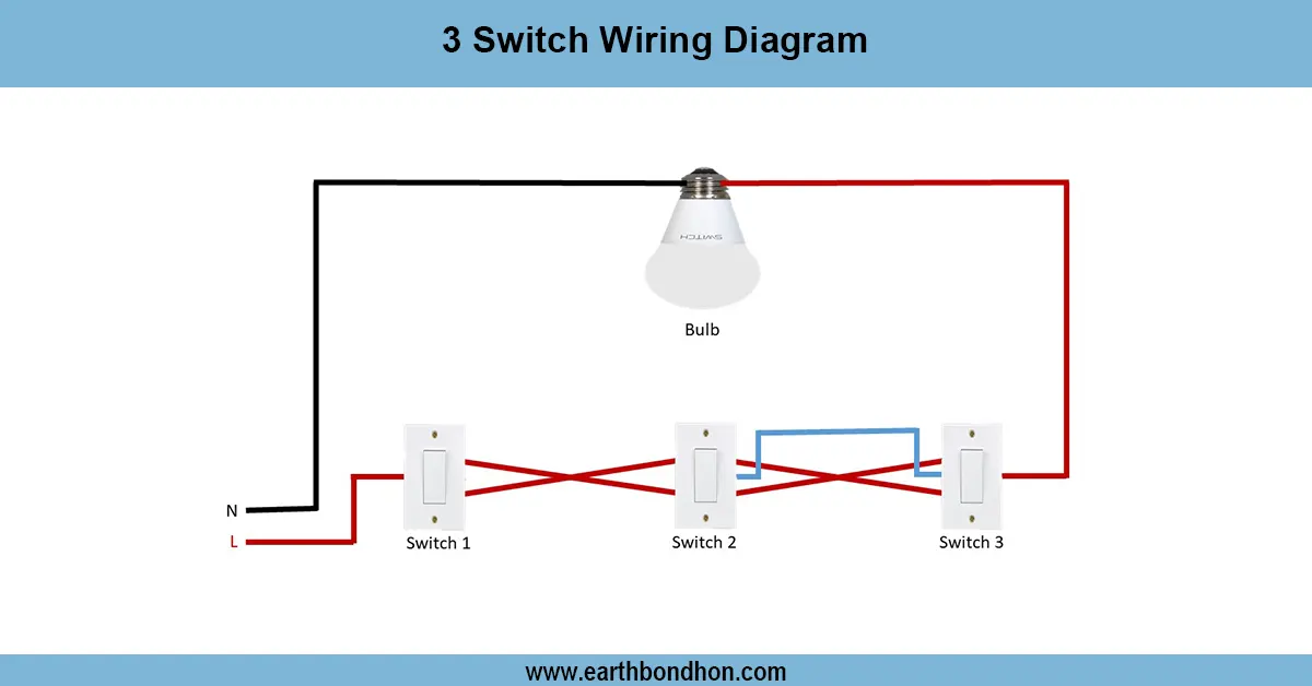
two room house wiring diagram
The diagram shows the entire wiring of a two-room house, comprising of supply, switches, lights, sockets, fans, MCBs and earthing, so that there is safe and efficient operation.
house wiring connection diagram for two rooms:
In this two-room whole house electrical wiring diagram, it is demonstrated how one can safely and effectively wire lights, sockets, switches, and appliances in a small house. Every room has light points, power outlets, and fan connections with control of wall switches. The supply is supplied to a main distribution board with MCBs, RCC, B, overload, and short circuit fuses. Earthing is done properly to provide safety, and the neutral connections stabilize the voltage. It is wired in standard phase and neutral colour codes so that it can be maintained easily. This configuration provides the possibility of control of lights and power outlets independently in each room and prevents failures in the system. The diagram also helps in ensuring that the installation is done in accordance with the safety standardsminimizesze energylossess makesmake troubleshooting easy.
Work & Installation (Input → Output,)
- Main Supply Connection: Feed main supply to the distribution board.
- Distribution Board: Install MCBs for each room and RCCB for overall protection.
- Room Wiring: Run phase (L) and neutral (N) wires to lights, sockets, and fans.
- Switches: Connect wall switches to control lights and ceiling fans.
- Sockets/Power Points: Connect outlets for appliances in each room, ensuring proper rating.
- Fan Wiring: Connect ceiling fans with regulator points if required.
- Earthing: Properly earth distribution board, switches, sockets, and metallic appliances.
- Labeling: Mark circuits for easy identification.
- Testing: Verify each light, fan, and socket works independently.
- Final Adjustment: Ensure all protective devices work and wiring is neat.
Testing & Final Adjustments
Wire and then switch ON the main supply. Check the lights, fans, and sockets in the two rooms separately. Wall switches to use with correct ON/ OFF. Check phase continuity, neutral continuity, and earth continuity with a multimeter. MCBs and RCCB Testing Check Connection Tripping Check Testing Check Tripping is also required to ensure the correct tripping when a fault occurs. Check cable connections to ensure that they are tight, insulated, and properly laid. Labeling: In the distribution board, label each circuit of the circuit board to make the circuit board easy to maintain. Check earthing resistance again and make sure that metallic fixtures are grounded. Test lights and fans several times to ensure that they work well. Proper testing and adjustments will result in energy savings, eliminate hazards associated with electricity,a nd grant the appliances a longer life span.