Circuit Before Throwing Exhausted Batteries
Build a circuit before throwing exhausted batteries to check and protect them. Step-by-step guide with circuit diagram, working principle, assembly, and troubleshooting for longer battery life.

Introduction to Battery Testing and Recovery Circuits
Untested disposal of batteries may result in the waste of potential energy. A battery test circuit will be used to find whether the battery is completely dead or it is merely low. It is also able to withstand low-voltage damage to sensitive devices. With the help of plain circuits, voltage or LED indicators can be checked, or a discharge load can be controlled to safely check battery health.
diy electronics projects
Test Before hurling exhausted batteries, it is often handy to test and perhaps restore some of the remaining charge. The circuit prior to throwing off the depleted batteries can be used to measure battery voltage, to show low or near-empty conditions, and to discharge or recharge safely, where possible. This is handy, especially with AA, AAA, 9V, lithium, or lead-acid batteries. This circuit, with the help of simple components such as resistors, capacitors, transistors, and LEDs, allows the visual indication of battery condition and does not allow the battery to be disposed of early. Here, we shall discuss the parts needed, operating concept, step-by-step assembly, circuit board, and troubleshooting hints, therefore, utilizing the maximum power of the battery, saving cash, and cutting down on the waste to the environment.
Features of the Battery Saver Circuit
Simple Design for All Battery Types
Compatible with AA, AAA, 9V, lithium, and lead-acid batteries. Minimal components make it easy for DIY projects.
Voltage and Charge Level Indication
LED indicators or a small display show charge levels. Red for low, yellow for medium, and green for good condition.
Automatic Cut-Off Protection
Prevents battery over-discharge and protects rechargeable batteries when discharging before disposal.
Components Required
Resistors
Used to set LED threshold voltages and limit current.
Capacitors
Stabilize readings and filter small voltage spikes.
Transistors or ICs
Transistors control the load. Optional ICs like LM3914 can create bar-graph style indicators.
LED Indicators
Red, yellow, and green LEDs show battery condition.
Power Supply (for recharge/testing)
Small DC supply used during testing or recharging low batteries.
Working Principle
Measuring Battery Voltage
Battery voltage is measured using dividers. Thresholds determine which LED lights up.
Detecting Low Battery Condition
Red LED activates when the battery voltage drops below the preset low threshold.
Load Management and Cut-Off
A transistor or MOSFET disconnects the battery from load when voltage is too low, preventing deep discharge.
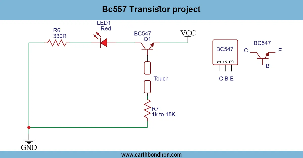
Circuit Diagram and Assembly Steps
Connecting Battery Terminals
Connect positive and negative battery terminals to the input. Use a series resistor for high-current batteries.
LED or Display Wiring
Connect LEDs through resistors for low, medium, and high voltage indications. Optional: use LM3914 for bar-graph display.
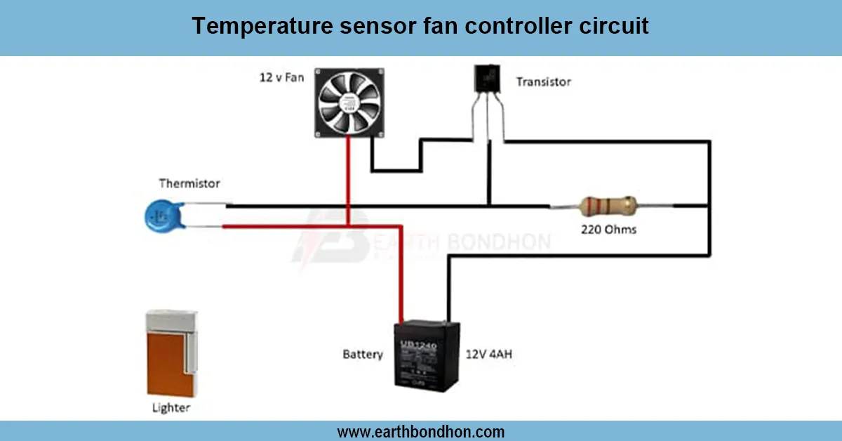
Adding Cut-Off Control
Place a transistor or MOSFET between battery and load. Trigger gate/base using comparator thresholds.
Testing and Adjusting Thresholds
Test different battery voltages, adjust resistors for accurate indication, and check auto cut-off functionality.
Applications
- Testing rechargeable and disposable batteries
- Safe disposal or recovery of near-dead batteries
- Educational battery behavior experiments
- Reducing waste and saving money
Safety Precautions
- Never short-circuit batteries.
- Avoid touching terminals of high-capacity batteries.
- Check polarity before connection.
- Use fuses for large batteries (e.g., lead-acid).
- Handle lithium batteries carefully to avoid fire hazards.
Troubleshooting and Maintenance
- LEDs not lighting: Check polarity and power supply.
- Incorrect readings: Verify resistor divider values.
- No cut-off: Inspect transistor/MOSFET trigger circuit.
- Overheating: Check load current and component ratings.
- Loose connections: Solder or tighten wiring.
Frequently Asked Questions - Circuit Before Throwing Exhausted Batteries:
Can this circuit test all types of batteries?
Yes, it can test AA, AAA, 9V, lithium, and lead-acid batteries.
How does the circuit indicate battery level?
Using LED indicators or a bar-graph display to show low, medium, and high charge.
Does it prevent battery over-discharge?
Yes, it has automatic cut-off using transistor or MOSFET.
Is it safe for lithium batteries?
Yes, if handled carefully and proper precautions are taken.
Can I use it to recharge batteries?
It can be used with a small DC supply for recharging during testing.
What components are needed?
Resistors, capacitors, transistor or ICs, LEDs, and power supply.
Can it save money by extending battery life?
Yes, by identifying batteries that still have usable charge.
Is this suitable for beginners?
Yes, it is simple to build and understand.
What voltage range does it support?
Typically 1.2V to 12V batteries; higher voltages require proper component ratings.
How do I adjust LED thresholds?
Change resistor values in the voltage divider to set LED voltage thresholds.