

Full Wave Bridge Rectifier Project
Learn how a full-wave bridge rectifier works using 4 diodes and a transformer. Explore working principles, circuit diagrams, and practical applications.

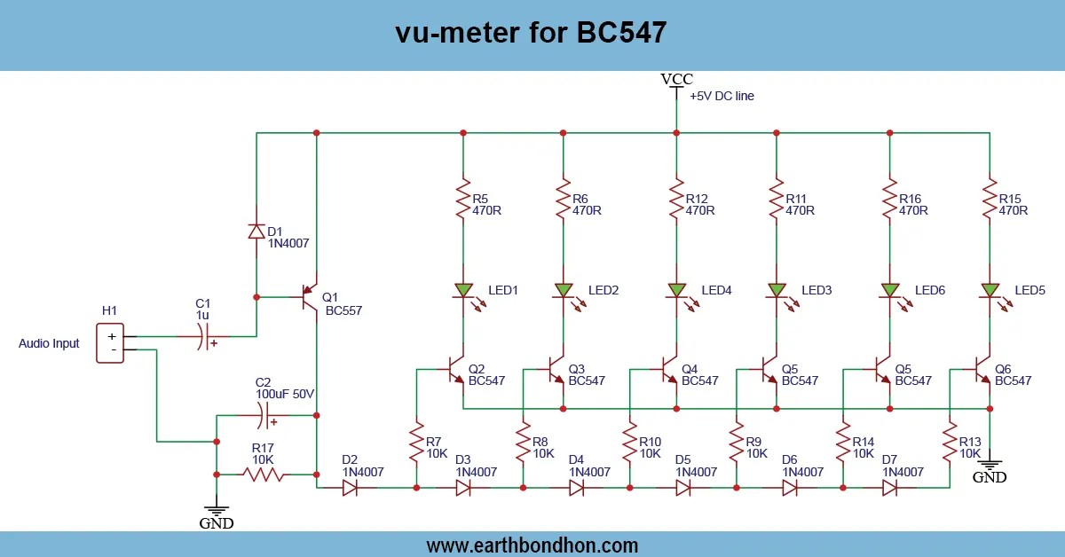
4 diode full-wave rectifier
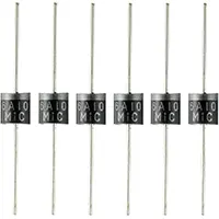
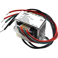
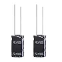
A circuit that converts AC (alternating current) to DC (direct current) by using 4 diodes organized in a bridge arrangement is also known as a full-wave bridge rectifier. This project contains the description of the circuit diagram, operating principle, and advantages of using a full-wave rectifier compared to a half-wave rectifier. The project is an essential yet practical project in power supply design, and is also an excellent project to perform as a student or when electronics are new to the student. It shows the alternating conductance of the diodes between each phase of AC, so that a smoother DC is generated. These comprise 4 diodes (1N4007), a center-tapped or a standard transformer, a filter capacitor, and a load resistor. This tutorial will have formulas, step-by-step explanations, and sample values of voltage to understand in better understand.
>Key Formulas for Full-Wave Bridge Rectifier:
- Vdc = (2 × Vm)/π ≈ 0.637 × Vm
- Vrms = Vm/√2
- Ripple Factor = (1.21 for full-wave)
- Efficiency = 81.2%
full-wave rectifier explanation
A full-wave bridge rectifier is a circuit that changes AC (alternating current) to DC (direct current) with four diodes connected in a most important position called the bridge position. This project describes the circuit, working principle, and benefits of a full-wave rectifier as compared to a half-wave rectifier. This project is of great importance in the design of power supply, a very important concept to students as well as beginners in electronics. It indicates how the diodes conduct alternating runs of the AC and make a smoother output of DC. It consists of 4 diodes (1N4007), a center-tapped or regular transformer and a filter capacitor, and a load resistor. Formulae, working explanations, and sample values of voltages are provided in this tutorial to understand.
bridge rectifier circuit
| AC Input (Vrms) | Transformer Vm | DC Output (Vdc) | Load Current (I) |
|---|---|---|---|
| 230V | 12V | 7.64V | 150mA |
| 110V | 6V | 3.82V | 75mA |