

Regulated adjustable Power Supply
Build a regulated adjustable power supply using LM317 IC. Provides stable, adjustable DC voltage for electronics projects, hobby circuits, and testing purposes.

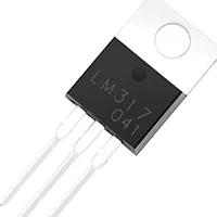
LM317 adjustable power supply
A DC voltage is obtained with an adjustable and controllable supply of power using the LM317. The output voltage to the hobby circuit, testing, and other educational electronics projects may be chosen by adjusting a resistor divider.
low-voltage magnetic sensor
The Regulated Adjustable Power Supply with LM317 is a flexible project to electronic hobbyists, offering a fixed and variable DC result in voltage. LM317 is a three-terminal variable voltage regulator IC that enables the voltage to be output between 1.25V and 37V with the correct input voltage and resistor values. It is a good power supply to use in hobby projects, experimental circuits, and learning experiments. Touching a resistor divider between the adjust pin and the output results in the selection of the exact wanted voltage. The inclusion of a capacitor input and output makes the operation low ripple and stable. Optional current-limiting resistors may be used to shield the power supply and devices used. Small, inexpensive, and simple to put together on a PCB or breadboard, this circuit is an indispensable part of DIY electronics laboratories.
Work / Installation (Inputs → Outputs)
- Input Supply → DC voltage higher than desired output (e.g., 12–40V).
- LM317 IC → Acts as an adjustable voltage regulator.
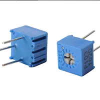
- Voltage Divider Resistors → Set output voltage.
- Capacitors → Filter input and output for stability.
- Output Load → Provides stable adjustable voltage to circuits.
- Installation → Assemble on PCB or breadboard, connect input voltage, resistors, capacitors, and load; measure output voltage and adjust resistors to desired value.
Testing & Final Adjustments
Once assemble,d turn on the circuit and place a multimeter on it. Use the voltage divider to adjust the value of the resistors to obtain the desired voltage. LM317 should have a good heatsink with increased currents. Load test at different loads to ensure that there is no drastic drop in voltage. To have a higher level of protection, add a fuse current-limiting resistor. Ensure that the input voltage is at all times greater than maximum output to ensure that it is regulated. Fine-tuning provides a stable, accurate, and safe hobby, electronics laboratory, or even DIY power supply. Reliability can be determined by proper testing to protect the LM317 IC and circuits.