Solar Panels in Parallel Diagram
Learn how a parallel connection increases current while keeping voltage constant. Step-by-step wiring, working principle, testing, and safety are explained.
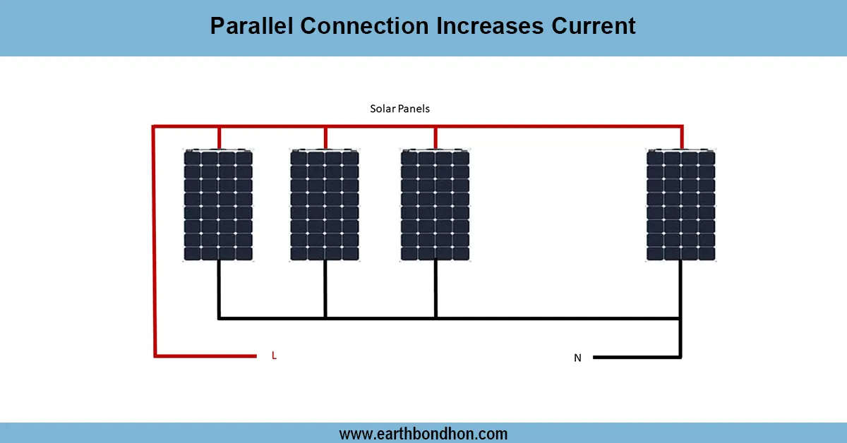
parallel connection increases current:
Parallel connection adds current since all the branches are at the same voltage, and the total current is the sum of the current of all loads connected to it. This necessitates parallel wiring where devices require a steady voltage and an increased supply of current.
home wiring parallel system:
Parallel connection is one of the most popular methods applied to electrical and electronic systems, as it allows current to grow and the voltage to remain constant. In a parallel connection, every positive terminal of the circuit is joined, and every negative terminal of the circuit is joined. This is to ensure that all branches have equal voltage supply, but the current is the sum of currents in each branch. As an illustration, three 12V, 5A solar panels connected in parallel will not only give 12V, but the current will be 15A. It can be applied to solar PV systems, battery banks, and household wiring (and other applications) with devices operating on the same operating voltage but requiring higher current. It also enhances the reliability of the system since failure in one branch does not affect the rest of the branches. Safe operation in parallel systems requires proper wiring, the proper size of cables, and protective devices.
⚡ Work & Installation (Input → Output):
Input: Power source → Positive to all positive terminals, negative to all negative terminals → Each branch receives the same voltage → Currents add together. Output: Increased total current capacity with constant voltage for connected loads.
Testing & Final Adjustments:
Once a parallel system has been wired, it is important to test it to make sure it is working properly and safely. Begin by measuring the voltage across any combination of branches; this should be equal to the supply voltage. Then, measure the current on each branch with a multimeter or clamp meter to ensure that the overall current is the sum of the current on the individual branches. Check all terminals to be tight and to have correct polarity, which will break or destroy loads or sources associated with reverse polarity. Test the cable sizes to make sure they can conduct the total current that has increased without getting hot. Protect against short circuiting by installing fuses or breakers on each branch. Conduct an insulation resistance test in case of long cable runs. Lastly, gradually start to energize the system, check the current flow, and make sure that all devices are functioning correctly. Implement necessary modifications, label connections, and document test results to maintain for the future. An appropriate test guarantees the correct operation and eliminates the chances of overheating, voltage drops, or fire risks in parallel wiring systems.