Solar Panel in Charge Controller Wiring Diagram
Learn solar panel wiring into a charge controller with battery and load connections for safe, efficient solar energy management in DC/AC systems.

solar panel charge controller wiring:
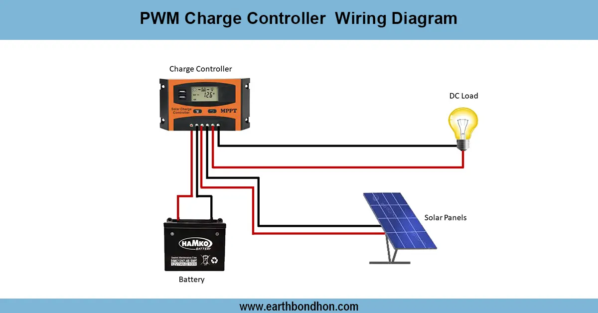
A charge controller wiring diagram includes a solar panel that guarantees solar energy charges the battery in a manner that is efficient and at the same time safe in powering DC or AC loads. The process of connecting in the right order will avoid damage and maximize performance.
home solar charge controller setup:
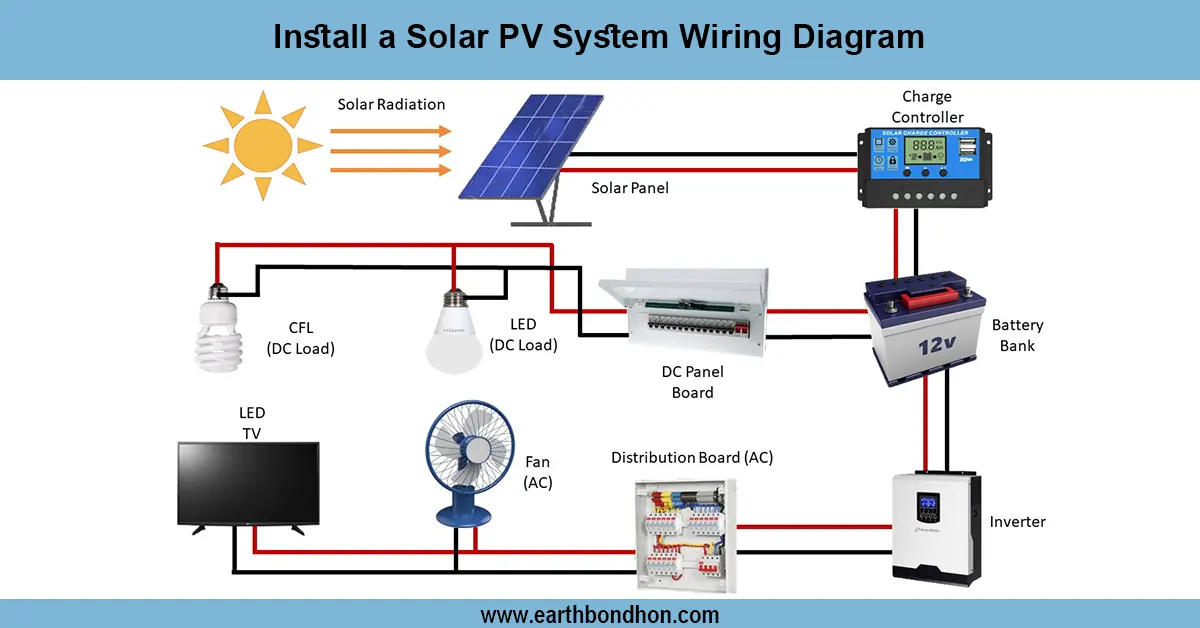
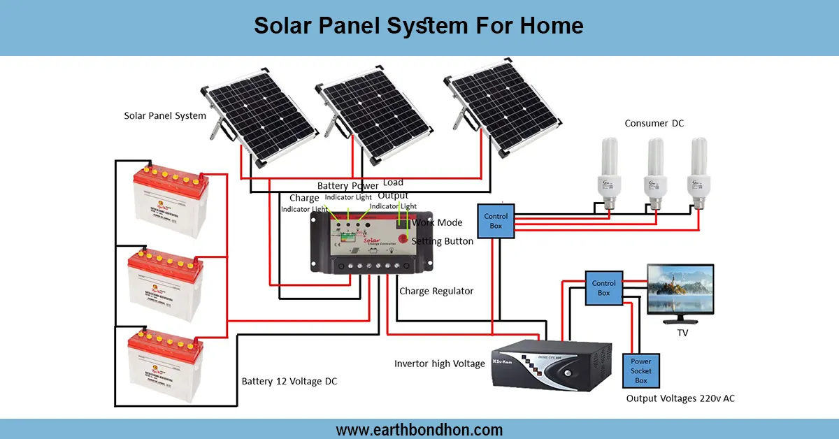
A charge controller solar panel in a charge controller wiring diagram demonstrates the safe connection of solar panels to a charge controller, battery, and loads. The charge controller also controls the amount of voltage and current being discharged by the solar panels to avoid excessive charging of the battery. Some of the common elements are the solar panel, PWM or MPPT charge controller, 12V/24V battery, DC loads, and an inverter (not mandatory) for AC appliances. To safeguard the controller and the battery, it is important to ensure that the wiring is done in the correct way, i.e,. Battery followed by Solar Panel, then Load. The positive and negative wires of the solar panel are connected to the PV input of the controller, the battery to the battery terminals, and DC or AC loads to the load terminals or inverter. Safe operation requires proper fuses, proper checking of cable size, and polarity. This circuit has wide usage across small home solar systems, off-grid systems, and backup systems to provide reliable energy management and efficient battery charging.
⚡ Work & Installation (Input → Output):
- Input: Solar panel generates DC power
- Step 1: Connect battery to controller (powers controller and sets system voltage)
- Step 2: Connect solar panel to PV input terminals
- Step 3: Connect DC loads or inverter to load terminals
- Output: Battery charges safely, DC or AC loads receive regulated power
Testing & Final Adjustments:
Once the solar panel has been wired into the charge controller, initially ensure that all the connections are of the correct polarity. Measure the open-circuit voltage (Voc) of the solar panel to ensure that the panel is within controller limits. Plug the battery and ensure that the controller switches on. Then, attach the solar panel to be able to flow charging current to the battery. Test DC loads by connecting them to the load and measuring the voltage across the load terminals. In case an inverter is used, this should be connected to the battery and the AC output The voltage is working. Check every terminal to make sure that it is well-connected and that the cable sizes are correct. Install a fuse in front of the solar panel and controller, as well as the controller and the battery, just to be on the safe side. safe side. Adjust bulk, flo, at, and load cut-off stage controller settings (where applicable). Test the system throughout the day in order to check its operation, correct battery charging, and ensure a constant load.
Frequently Asked Questions - Solar Panel in Charge Controller Wiring Diagram:
How do I wire a solar panel to a charge controller?
Connect the battery first, then the solar panel to the PV input, and finally the loads or inverter.
Why connect battery first?
The controller needs the battery to set system voltage and prevent panel damage.
Can I use PWM or MPPT controller?
Yes, PWM is for small systems; MPPT is more efficient for larger systems.
Do I need fuses in the wiring?
Yes, install fuses between solar panel and controller, and controller and battery.
What voltage system can be used?
12V, 24V, or 48V DC systems depending on controller and battery ratings.
Can I connect AC loads?
Yes, through an inverter connected to the battery.
What happens if polarity is reversed?
Reversed polarity can damage the controller, battery, and connected loads.
How to test solar panel charging?
Measure battery voltage and charging current, verify controller display or LEDs.
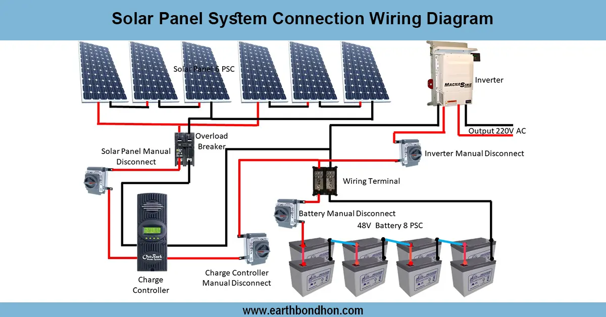
Can multiple solar panels be connected?
Yes, in series for voltage or parallel for current, depending on system requirements.
Is this setup safe for home use?
Yes, with proper fuses, cable sizing, and correct polarity, it is safe and reliable.