Solar Charge Controller Wiring
Step-by-step PWM charge controller wiring diagram with solar panel, battery, and inverter connections for safe, efficient off-grid solar systems.

pwm charge controller wiring diagram:
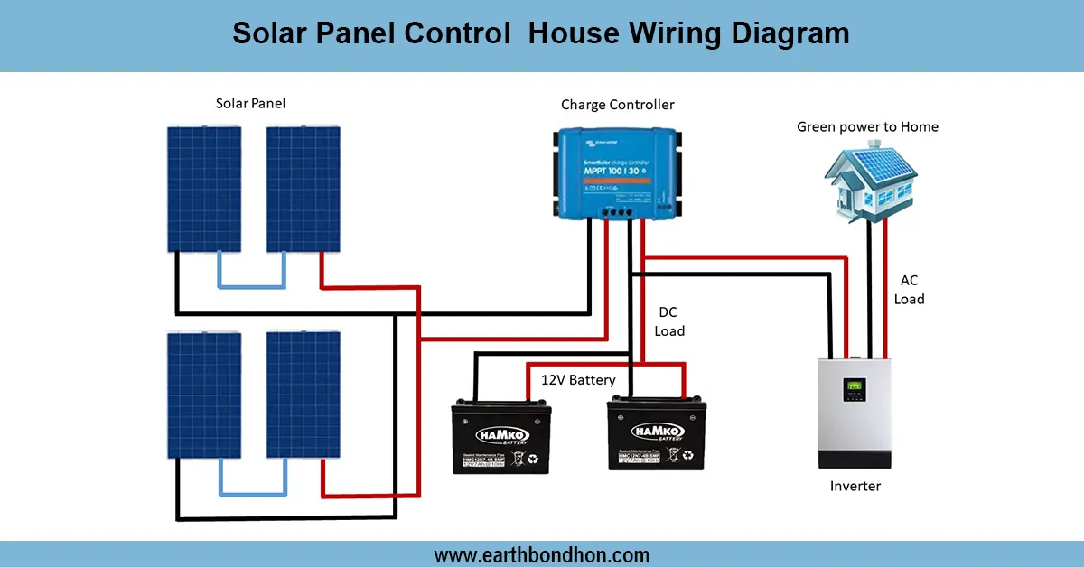
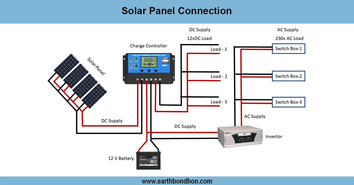
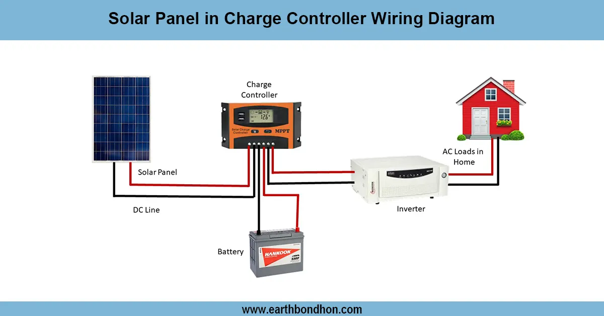
A PWM charge controller wiring diagram shows how to connect a solar panel to the controller, then to the battery, and finally to the inverter or load. The correct sequence is battery first, then solar, then load, ensuring safe charging and stable operation.
pwm charge controller setup:
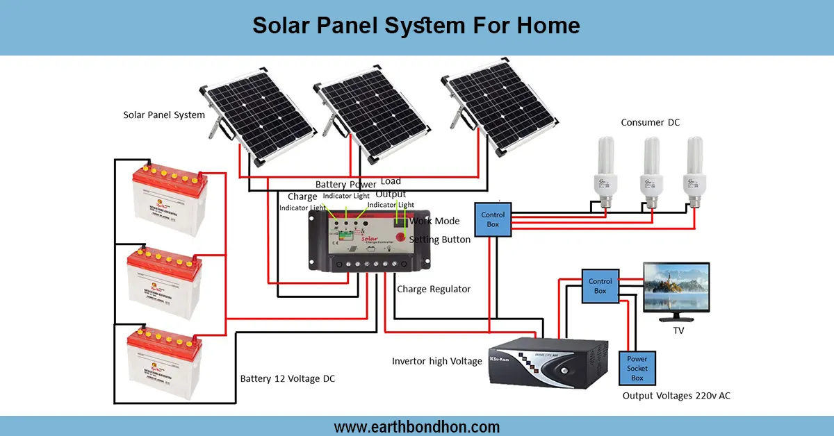
One of the most popular devices in small to medium-sized solar systems is a PWM (Pulse Width Modulation) charge controller. It controls the way the battery is charged by turning the solar panel voltage down to battery voltage to avoid overcharging and increase battery life. To connect a PWM charge controller, you only need to have a battery connected to the controller to make it happy, and then have the solar panel connected to the input connector, and lastly, the load or inverter connected to a load connector when it has one. When connecting battery, solar, and load, always ensure that you have the sequence battery, then solar, then load. In a standard wiring diagram, the positive/negative wires of the solar panel are attached to the PV input of the controller, the battery is attached to the battery posts, and the inverter or DC loads are attached to the load post. Proper cable sizing, fuse protection, and polarity. There should be proper checks on cable sizing, fuse protection, and polarity. PWM controllers are suitable when using small off-grid 12 V / 24 V systems where the cost-effectiveness and reliability are of importance.
⚡ Work & Installation (Input → Output):
- Input: Solar panel DC power → Controller reduces voltage to match battery
- Process: PWM regulates charging by switching voltage pulses
- Output: Stable battery charging and safe power to loads/inverter
Testing & Final Adjustments:
Once the PWM charge controller has been wired, check the polarity with a multimeter. First, you can attach the battery and determine whether the controller is turned on. Next, attach the solar panel and make sure that there are indicators or a display of current flow. Lastly, plug in the load or inverter and ensure that the voltage output is constant. Ensure that the controller shows the battery charging stages (bulk, absorption, float). Check the tightness of terminals, the correctness of fuses or breakers. Measure open-circuit voltage (Voc) of the solar panel to ensure that it is within the voltage range of the controller. Test load current draw, also, against the controller rating. Should the system be 12v or 24v, ensure that the auto-detected or manually set system voltage is correct. Set load cut-off or battery protection settings to your own liking. Interconnect the document wiring, label terminals, and check the performance during a period of 24 hours to maintain reliability. Safety and long-term effectiveness of the PWM controller system are guaranteed by proper testing.
Frequently Asked Questions - Solar Charge Controller Wiring:
What is a PWM charge controller?
A PWM charge controller regulates solar panel voltage to safely charge batteries by using pulse width modulation.
How do you wire a PWM charge controller?
First connect the battery, then solar panel, then load/inverter to the controller following polarity marks.
Why connect the battery first?
The battery powers the controller and sets the system voltage, preventing damage to the controller or panels.
Can I connect inverter directly to PWM controller?
Yes, if the controller has load terminals; otherwise, connect inverter directly to battery with proper fuse.
What voltage is suitable for PWM?
PWM controllers work best with 12V and 24V solar systems, usually up to 48V in some models.
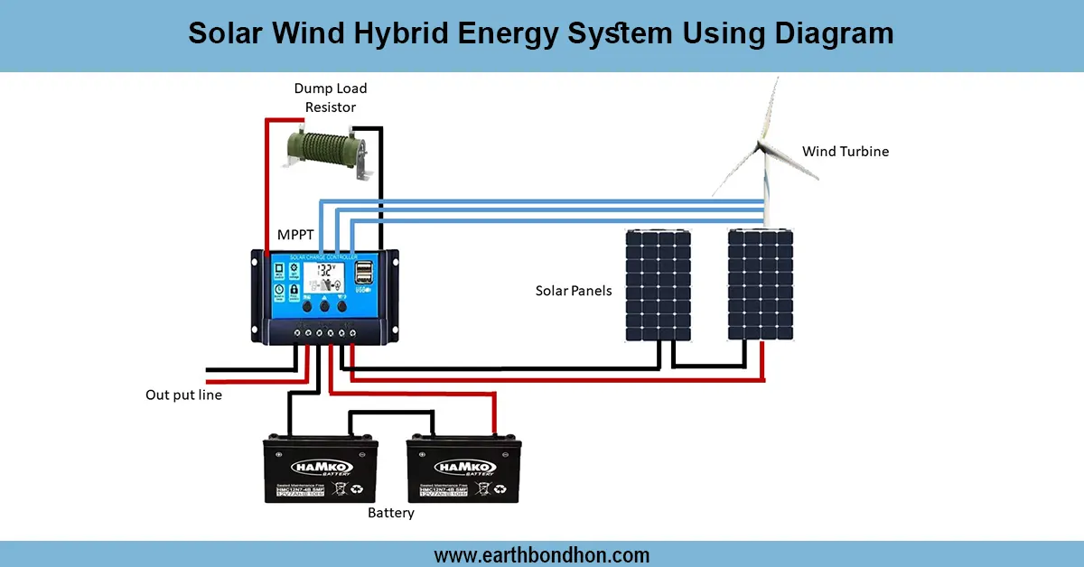
What is the difference between PWM and MPPT?
PWM lowers panel voltage to match battery, while MPPT converts higher panel voltage for higher efficiency.
Do I need a fuse with PWM controller?
Yes, install fuses between solar panel and controller, and between controller and battery for protection.
How do I test a PWM charge controller?
Check system voltage, measure charging current, verify LED or LCD indicators, and monitor battery levels.
What happens if polarity is reversed?
Reversed polarity can damage the controller; always check with a multimeter before final connection.
Is PWM suitable for large systems?
No, PWM is more efficient for small off-grid systems; large systems usually use MPPT controllers.