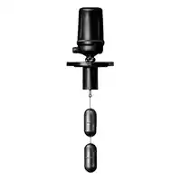
Float switch wiring diagram:
This diagram shows how to make a float switch wiring diagram. In this circuit, we use DP MCB ( Double Pole Minature Circuit Breaker ), an RCCB ( Residual Current Circuit Breaker ), a magnetic contactor, a push switch, and a flowmeter. First, we need to connect the DP MCB ( Double Pole Minature Circuit Breaker ), then connect the RCCB, then connect the motor protection, then connect the contactor motor and flowmeter with this circuit.
Advertisements
Diagram of Float switch wiring:

Components needed For this Project:
You can get the components from any of the sites below:
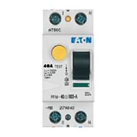
- DP MCB 20A [See Buy Click Amazon]
- DP RCCB 16A [See Buy Click Amazon]
- MPCB Switch [See Buy Click Amazon]
- Magnetic Contactor 40A [See Buy Click Amazon]
- Push Button NO Switch [See Buy Click Amazon]
- Flow Meter [See Buy Click Amazon]
- Single Phase Motor (1 HP) [See Buy Click Amazon]
*Please note: These are affiliate links. I may make a commission if you buy the components through these links. I would appreciate your support in this way!
Advertisements
Components used to make the Float switch wiring diagram:
01. DP MCB:

DP MCB In 2 Pole MCB, switching & protection is affected in phases and the neutral. A Double Pole or DP Switch is a Switch that Controls 2 Circuits at the same time. In terms of Residential Switching, this Normally means it Switches the live and Neutral at the same time. In Layperson Terms, Double Pole switches or DP Switches are Exclusively Designed to Control 2 Different Electrical Circuits at the same time, which allows the Appliances to Isolate safely and reliably. Fan or light Combinations and Medical Equipment are some of the many applications for DP Electrical Switches and Electrical components.
02. RCCB:
The Residual Current Circuit breaker RCCB is the Safest device to detect and Trip against Electrical Leakage current. This ensures protection against Electric shock Caused by indirect contact. Circuit breakers (CB) are automatically Operated Electrical Switches that Protect Electrical Circuits from Short-Circuiting or Overloading systems. It Protects against many major accidents. RCCB Circuit Breaker is an Electrical Wiring device whose function is to disconnect the current in the circuit.
03. MPCB Motor Protector:
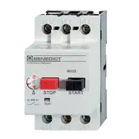
MPCB = Motor Protection Circuit Breakers. A protection system against electrical faults, such as short circuits for AC Line 220V. line-to-ground faults, and line-to-line faults. Electrical faults that are below the MPCB is breaking capacity can be interrupted by the board.MCBs are designed for a wide variety of functions circuit protection functions while MPCBs are used for the specific function of protecting circuits driving electric motors.
04. Magnetic Contactor:
A magnetic contactor is an electromagnetic switching device. It is generally used for controlling 3-phase Motors. The operation of a magnetic contactor is similar to that of a Relay. but a relay is used for low-power or low-voltage connections, and a magnetic contactor is used for high-power or high-voltage connections. As soon as the supply is applied to the magnetic contactor coil. its normally open contacts are closed and normally closed contacts are opened and the associated devices are also operated. This is how a magnetic contactor works.

05. Push Switch:

NO (Normally Open) Terms Refer to a Type of Dry Contact or Wet Contact. A Push to Make Switch Allows Electricity to flow Between its 2 contacts when held in. When the button is released, the Circuit is broken. This type of Switch is also known as A Normally Open (NO) Switching system. As its name implies, a Normally Open (NO) Switch Contact or “a Contact” is a Switch. Put very simply, a Normally Open Sensor will have no Current When in a Normal State But When it Enters an Alarm State it will have +5V applied to the Circuit.
06. Flowmeter:
Water flow meters are devices used to measure the volume or mass of fluid that passes through a pipe for water. They are commonly used in water flow treatment and distribution systems, irrigation, and industrial processes. There are several types of water flow meters set, including positive displacement meters, turbine meters, ultrasonic meters, and magnetic meters. A water flow meter measures the total volume of fluid that has passed through a pipe over a certain time. A water flow sensor, on the other hand, measures the velocity of the fluid flow at a specific point in time. It is mainly used to monitor the flow rate in real-time, to detect any changes or irregularities in the water flow, and to regulate or control the flow as needed.
07. Single Phase Motor:

A Single-Phase Motor is an Electrically-Powered Rotary Machine That Can Turn Electric Energy into Mechanical Energy. It Works by Using a Single-Phase Power Supply. Single-phase Motors Are Used in Equipment And Machines That Are Smaller in Size And Require Lower Horsepower. This Includes Equipment Such As Refrigerators, Pumps, Compressors, Fans, and Portable Drills. Single-phase motors Have a Similar Construction to The 3-phase Motor, Including an AC Winding That is Placed on The Stator And Short-Circuited Conductors That are Placed in a Cylindrical Rotor.
Thank You for visiting the website. Keep visiting for more Updates.
Frequently asked questions
A cable float switch is used in liquids for control or signal activation and operates by responding to the liquid level. It is also suitable for use in sewage. Automatic control of pump stations. Earth protection.
100 V – 250 V depending on the type of reed contact (please refer to Page 130). The float magnet initiates a switching signal by magnetizing the contact studs of the reed contact.
Float-level switches are sensors with an electrical contact of the output at a specific liquid level. Applications include level control, valve control, deaerators, condensate tanks, oil level control, drip legs, or boilers.
The float level is set manually and is a critical position. Too low and not enough gas. Too high and gas could flood into the carburetor mixing chamber. This will either choke the engine or start a fire. So the float of the level must be positioned just correctly to maintain the proper level of gas in the float bowl.
A specific float switch would be rated to handle a set electrical load. If the load exceeds the rating of the switch, the heat could damage the contacts in the switch or cause it to malfunction.
Read more Single Phase Wiring
What is a kilowatt-hour (kWh) | kwh formula | What does kwh mean
Introduction to Electrical Units and CircuitskW and kWh on your electricity bill As your home uses electricity during...
What is the Difference Between kVA | What does KVA mean | kVA formula
Difference Between KVA ExplainedWhat does KVA Mean? There are technical terms aplenty when it comes to generators, and...
Power Factor | Power Unit | Energy | Electricity Unit
Power factor definition | Calculating Power FactorPower Factor Values In a purely resistive circuit, the power factor...
0 Comments