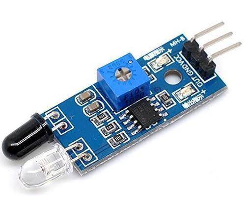
Infrared Sensor
An Infrared LED (IR LED) may be a special-purpose LED emitting infrared rays starting from 700 nm to 1 mm wavelength. Different IR LEDs may produce infrared of differing wavelengths, a bit like different LEDs produce light of various colors.
IR LEDs are usually made from gallium arsenide or aluminum gallium arsenide. In complement with IR receivers, these are commonly used as sensors.
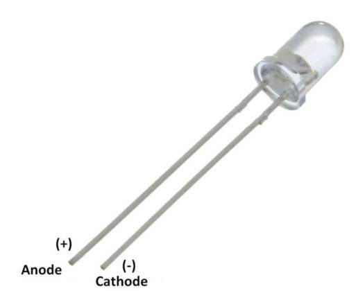
The appearance of the IR LED is the same as a standard LED. Since the human eye cannot see the infrared, it’s impossible for an individual to spot if an IR LED is functioning. A camera on a telephone camera solves this problem. The IR rays from the IR LED within the circuit are shown within the camera.
Pin Diagram of IR LED
An IR LED may be a sort of diode or simple semiconductor. current is allowed to flow in just one direction in diodes. because the current flows, electrons fall from one a part of the diode into holes on another part. so as to fall under these holes, the electrons must shed energy within the sort of photons, which produce light.
It is necessary to modulate the emission from IR diode to use it within the electronic applications to stop spurious triggering. Modulation makes the signal from IR LED stand out above the noise. Infrared diodes have a package that’s opaque to light but transparent to infrared. the huge use of IR LEDs in remote controls and safety alarm systems has drastically reduced the pricing of IR diodes within the market.
Principle of Working
An IR sensor consists of two parts, the emitter circuit, and therefore the receiver circuit. this is often collectively referred to as a photo-coupler or an optocoupler.
The emitter is an IR LED and therefore the detector is an IR photodiode. The IR photodiode is sensitive to the IR light emitted by an IR LED. The photo-diodes resistance and output voltage change in proportion to the IR light received. this is often the underlying working rule of the IR sensor.
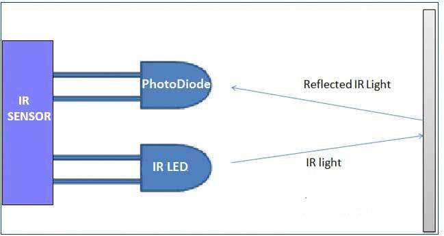
The type of incidence is often direct incidence or indirect incidence. In direct incidence, the IR LED is placed ahead of a photodiode with no obstacle in between. In indirect incidence, both the diodes are placed side by side with an opaque object ahead of the sensor. the sunshine from the IR LED hits the opaque surface and reflects back to the photodiode.
FEATURES
1. Package type: leaded.
2. Detector type: photo-transistor.
3. Peak operating distance: 2.5 mm.
4. Operating range within > 20 % relative.
5. collector current: 0.2 mm to 15 mm.
6. Typical output current under test: IC = 1 mA.
7. Daylight blocking filter.
8. Emitter wavelength: 950 nm.
9. Lead (Pb)-free soldering released.
SPECIFICATIONS:
1. IR sensor with transistor output.
2. Operating Voltage:5V.
3. Diode forward Current: 60mA.
4. Output: Analog or digital data.
5. Transistor collector current: 100mA.
6. Operating temperature: -25°C to +85°C
APPLICATIONS:
Commonly used in proximity detection applications
1. Line follower or maze solver robots
2. Distinguish between reflective and non-reflective surface
3. Obstacle detection and avoidance
4. 2D-Model
5. Position sensor for shaft encoder
6. Detection of reflective material such as paper, IBM cards, magnetic tapes.
7. Limit switch for mechanical motions.