Motor control circuit diagram with PLC:
This Diagram shows the Motor control circuit diagram with PLC. In this circuit, we use a PLC and a 3-Phase Motor. This circuit diagram is very simple and easy to make. If you want to know more details about this circuit please check our youtube video below the post. Please stay with our website for more updates about electrical electronics and robotics projects gadgets and circuits.
Diagram of Motor control circuit diagram with PLC:

Components needed For this Project:
You can get the components from any of the sites below:
- PLC [See Buy Click Amazon]
- Terminal Block [See Buy Click Amazon]
- 3 Phase Motor[See Buy Click Amazon]
*Please note: These are affiliate links. I may make a commission if you buy the components through these links. I would appreciate your support in this way!
Components used to make the Motor control circuit diagram with PLC:
01. PLC:
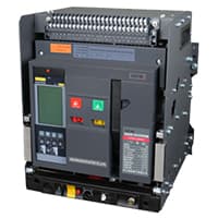
PLC (PLC) full name Programmable Logic Controller (Programmable Logic Controller). It is a device that can easily control other devices. It is a type of industrial computer control system that will make a decision depending on the custom program and control the output as soon as any signal is received at the input. A PLC usually consists of a microprocessor that has to be programmed by a computer. The program is basically written in computer software and it is loaded to the PLC with the help of a cable.
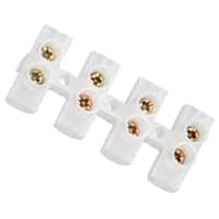
02. Terminal Block:
Terminal Clocks are Connectors That Terminate a Single wire and Connect it to a circuit or other system. Terminal Blocks come in a range of shapes, Sizes, and ratings, but Always Terminate a single Wire and are Never multi-pole. Terminal Blocks are used to Secure and/or Terminate Wires and, in Their Simplest form, Consist of Several Individual Terminals Arranged in a long strip. Terminals are Useful for Connecting the Wiring to the Ground or, in the Case of Electrical power, for Connecting Electrical Switches and Outlets to the Mains.
03. 3-Phase Motor:

A Three-Phase electric motor uses a 3-Phase Power Supply to Convert Electric Energy into Mechanical Energy. It contains four Wires (Three hot Wires and one Neutral Wire) and Uses 3 Alternating Currents of the Same Frequency. Since it Generates a Rotating Magnetic Field, it does not need a Capacitor for the Startup. Some Three-Phase Motors are Reversible, Which Means they can serve as Generators by Turning Mechanical Energy into Electrical Energy.
Thank You for visiting the website. Keep visiting for more Updates.
Read more Single Phase Wiring
PLC Motor Control Circuit
PLC Motor Control Circuit: This Diagram shows PLC Motor Control Circuit. In this circuit, we use a PLC and a 3-Phase...
Star delta starter wiring plc program
Star delta starter wiring plc program: This Diagram shows the Star delta starter wiring plc program. In this circuit,...
Working principle of PLC
Working principle of PLC: This Diagram shows how to make the Working principle of PLC. In this circuit, This circuit...
0 Comments