Photocell Wiring Diagram:
This diagram shows how to make photocell connections. Photocell wiring diagram. In this circuit, we use a day-night sensor, a light, an SP MCB ( Single Pole Miniature Circuit Breaker ), and a switch. First, we need to input phase connection to the SP MCB, then input phase connection to switch and day night sensor and light, then input neutral connection to day night sensor & light. If you want to know more about this circuit please check our youtube video below the post.
Advertisements
Diagram of Photocell Wiring:

Components needed For this Project:
You can get the components from any of the sites below:
- CFL Light [See Buy Click Amazon]
- SP MCB 10A [See Buy Click Amazon]
- Gang Switch [See Buy Click Amazon]
- [day_night_sensor]
*Please note: These are affiliate links. I may make a commission if you buy the components through these links. I would appreciate your support in this way!
Advertisements
Components used to make the Photocell Wiring Diagram:
01. CFL Light:

CFL stands for Compact Fluorescent Lamp which is an improved version of tube lights of earlier days. Like tube lights, it is a vacuum glass tube with fluorescent powder coating which is not as long and straight as tube lights but curved/twisted compact, or small in size. Like a tube light, it has electrodes or filaments at both ends. But in this case, instead of a choke, there is an electronic circuit that drives the Compact Fluorescent Lamp. Because the red wave is less in the light of the Tubelight and Compact Fluorescent Lamp, the object looks a little pale or the correct color of the object does not appear.
02. SP MCB:
In single-pole MCB, Switching and protection are Affected in only one Phase. Single phase supply to break the phase only. A single Pole breaker is Typically used with 120-volt Circuits, and a 6-20 amps Miniature Circuit Breaker. They are constructed with one Line Wire and one Neutral wire. A Single Pole switch is the most basic General-Purpose switch that you use to Control a light or another device from one location. These Switches have 2 Brass-Colored screw Terminals Connected to the hot Power source wires. Pole refers to the number of Circuits Controlled by the Switch SP Switches Control only one Switch Electrical Circuit.

03. Switch:

An SPST (Single Pole Single Throw) Switch is a Switch That only Has a Single Input and can Connect Only to one Output. This means it Only Has one Input Terminal and Only 1 Output Terminal. A Switch is a Mechanical or Controlling Device That Changes the Flow of Current Direction or Interrupts the Flow of Current Within a Circuit diagram. An electrical line using Single Pole Single Throws (SPST) is Perfect for on-off switching. When the SPST is closed, the Circuit is Closed and the light from the lamp switches on the system. When The Single Pole Single Throw (SPST) is then opened, the light from the lamp goes out and the Circuit is off.
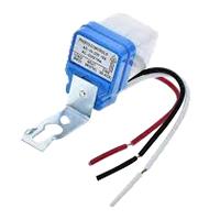
04. Day Night Sensor:
Thank You for visiting the website. Keep visiting for more Updates.
Read more Single Phase Wiring
What is a kilowatt-hour (kWh) | kwh formula | What does kwh mean
Introduction to Electrical Units and CircuitskW and kWh on your electricity bill As your home uses electricity during...
What is the Difference Between kVA | What does KVA mean | kVA formula
Difference Between KVA ExplainedWhat does KVA Mean? There are technical terms aplenty when it comes to generators, and...
Power Factor | Power Unit | Energy | Electricity Unit
Power factor definition | Calculating Power FactorPower Factor Values In a purely resistive circuit, the power factor...
0 Comments
Trackbacks/Pingbacks