Timer Relay Wiring Diagram:
This diagram shows how to make timer relay wiring. In this circuit, we use a DP MCB ( Double Pole Miniature Circuit Breaker ), a push relay, a neutral busbar, and two switches. First, we need to input the power to the DP MCB, then input power to the neutral busbar, then input power to the light and switch. Now this circuit is ready for use. if you want to know more about this circuit please check our youtube video below the post.
Advertisements
Diagram of Timer Relay Wiring Diagram:

Components needed For this Project:
You can get the components from any of the sites below:
- DP MCB 16A [See Buy Click Amazon]
- Busbar wire [See Buy Click Amazon]
- Digital Relay 220V AC [See Buy Click Amazon]
- CFL Light [See Buy Click Amazon]
- SPST Switch [See Buy Click Amazon]
*Please note: These are affiliate links. I may make a commission if you buy the components through these links. I would appreciate your support in this way!
Advertisements
Components used to make the Timer Relay Wiring Diagram:
01. DP MCB:

DP MCB In 2 Pole MCB, switching & protection is affected in phases and the neutral. A Double Pole or DP Switch is a Switch that Controls 2 Circuits at the same time. In terms of Residential Switching, this Normally means it Switches the live and Neutral at the same time. In Layperson Terms, Double Pole switches or DP Switches are Exclusively Designed to Control 2 Different Electrical Circuits at the same time, which allows the Appliances to Isolate safely and reliably. Fan or light Combinations and Medical Equipment are some of the many applications for DP Electrical Switches and Electrical components.
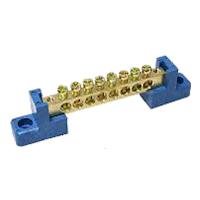
02. Busbar:
A busbar is a type of Electrical conductor. It is made of copper brass or aluminum. Busbar is most commonly used in factories. We supply the power from the transformer to the busbar. We take the electricity from this busbar to the circuit breaker. The advantage of using a busbar is that through it we can provide multiple power connections in multiple places very easily. How many thick copper bars are aggregates of busbars? A copper bar is rectangular (rectangular) copper type or triangular in shape.
03. Relay:
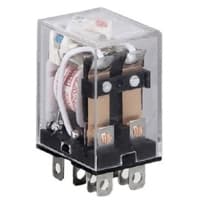
The most popular relay for automation work is the 8 Pin Relay. The 8-pin relay has a DC or AC coil as the main part. which is connected to two pins. There are two common parts. Underneath a Common part are a NO and an NC part. No part is normally open with a common part and the NC part is normally closed. The timer base used for automation is the same as the 8-relay base. That is, switching can be done using the timer base. This is basically how a relay switch works for the relay.
04. CFL Light:
CFL stands for Compact Fluorescent Lamp which is an improved version of tube lights of earlier days. Like tube lights, it is a vacuum glass tube with fluorescent powder coating which is not as long and straight as tube lights but curved/twisted compact, or small in size. Like a tube light, it has electrodes or filaments at both ends. But in this case, instead of a choke, there is an electronic circuit that drives the Compact Fluorescent Lamp. Because the red wave is less in the light of the Tubelight and Compact Fluorescent Lamp, the object looks a little pale or the correct color of the object does not appear.

05. SPST Switch:

An SPST (Single Pole Single Throw) Switch is a Switch That only Has a Single Input and can Connect Only to one Output. This means it Only Has one Input Terminal and Only 1 Output Terminal. A Switch is a Mechanical or Controlling Device That Changes the Flow of Current Direction or Interrupts the Flow of Current Within a Circuit diagram. An electrical line using Single Pole Single Throws (SPST) is Perfect for on-off switching. When the SPST is closed, the Circuit is Closed and the light from the lamp switches on the system. When The Single Pole Single Throw (SPST) is then opened, the light from the lamp goes out and the Circuit is off.
Thank You for visiting the website. Keep visiting for more Updates.
Read more Single Phase Wiring
What is a kilowatt-hour (kWh) | kwh formula | What does kwh mean
Introduction to Electrical Units and CircuitskW and kWh on your electricity bill As your home uses electricity during...
What is the Difference Between kVA | What does KVA mean | kVA formula
Difference Between KVA ExplainedWhat does KVA Mean? There are technical terms aplenty when it comes to generators, and...
Power Factor | Power Unit | Energy | Electricity Unit
Power factor definition | Calculating Power FactorPower Factor Values In a purely resistive circuit, the power factor...
0 Comments