
Pir Motion Sensor Light Wiring Diagram
Learn complete house motion sensor wiring for lights and alarms, including sensor connections, power supply, and safe operation for automated home control.

automatic light sensor connection
The House motion sensor wiring system is an automatic system that operates lights and alarms by motion sensor. Correct wiring will guarantee the stability, security, and eco-friendliness of functioning.
indoor outdoor motion sensor setup
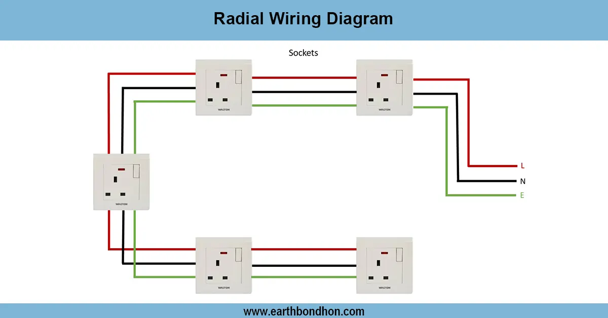
The entire house motion sensor wiring diagram indicates how to wire the sensors to turn lights, alarms, or other objects on and off automatically. Motion sensors (PIR or ultrasonic) are motion sensors used to sense motion and act on a relay or directly to lights. The wiring has live, neutral, and earth connections and optional manual override switches. Installation should be done in a proper manner such that the installation is reliable, prevents false triggering, and protects the circuit by use of fuses or MCBs. The sensors are usually placed at the doorways, in corridors, or on the outdoor side to have maximum coverage. There are systems where several sensors are used to operate one light or alarm, and some that may be used to operate different devices in various rooms. Testing includes testing the detection range, sensor sensitivity, and proper timing of activation/deactivation. Home automation systems should be well labelled and positioned to enhance usability and safety.
Work & Installation (Input → Output Summary)
- Connectlive, neutral, and earth to the motion sensor power terminals.
- Wireoutput terminals of the sensor to the load (light, alarm, or relay).
- Install optionalmanual override switch in series with the load.
- Mount sensors atentrances, corridors, or outdoor areas for optimal coverage.
- Ensurefuse or MCB protection in the circuit.
- Test sensor detection range and delay settings.
- Adjust sensitivity to prevent false triggers.
- Connect multiple sensors if required for combined control.
Testing & Final Adjustments
- Verify power supply wiring: live, neutral, and earth.
- Check sensor output activates the connected load when motion is detected.
- Adjustdetection range and time delay according to room size.
- Test each sensor individually to ensure coverage.
- Check forfalse triggering from pets, air movement, or sunlight.
- Ensurefuse/MCB protection fuse/MCB protection is functional.
- Inspect all connections for secure terminals and insulation.
- Perform multiple motion tests at different locations.
- Verify manual override switch operates as intended.
- Document sensor placement, wiring, and settings for maintenance.
Frequently Asked Questions - Pir Motion Sensor Light Wiring Diagram:
What is a motion sensor?
A device that detects movement and activates lights, alarms, or other devices.
How is it wired in a house?
Connect live, neutral, and earth to the sensor and output to the load.
Can multiple sensors control one light?
Yes, sensors can be wired in parallel to control a single load.
Is earth connection necessary?
Yes, for safety and reliable operation.
How to prevent false triggering?
Adjust sensitivity and avoid mounting near heat sources or air vents.
Can I add a manual switch?
Yes, a manual override can be added in series with the load.
What loads can be controlled?
Lights, alarms, relays, fans, or other electrical devices.
Do I need fuse or MCB protection?
Yes, to protect the sensor and connected devices.
Where should sensors be mounted?
Entrances, corridors, driveways, or areas with motion detection needs.
How to test a motion sensor?
Power on, move in the detection area, and observe activation of connected load.