Series Parallel Switch Wiring Diagram:
This diagram shows how to make a Series Parallel Switch Wiring. In this circuit, we use a fuse, an indicator light, 2 switches, two 2-pin sockets, and a light holder. First, we need to connect the fuse in the phase line, then input the phase line to all switches and sockets’ phase points. Then we need to connect the holder and indicator like in our diagram. Now this circuit is ready for use. If you want to know more about this circuit please check our youtube video at the below post.
Advertisements
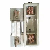
Diagram of Series Parallel Switch Wiring diagram:

Components needed For this Project:
You can get the components from any of the sites below:
- Cutout Fuse [See Buy Click Amazon]
- SPST Switch [See Buy Click Amazon]
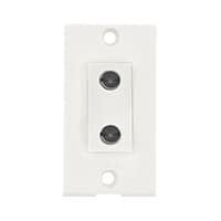
- 2 Pin Socket [See Buy Click Amazon]
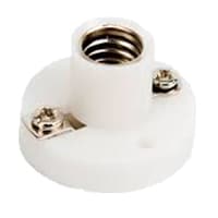
- Light Holder [See Buy Click Amazon]
- Board Indicator [See Buy Click Amazon]
*Please note: These are affiliate links. I may make a commission if you buy the components through these links. I would appreciate your support in this way!
Advertisements
Components used to make the Series Parallel Switch Wiring:
01. Fuse:
A fuse cuts off the current when the current exceeds a safe value due to short-circuiting or overloading. When the current becomes large it heats the fuse wire too much. Since the melting point of fuse wire is low it melts and breaks the circuit diagram. Cartridge fuses are low-cost electrical safety devices that are used for the overload protection of electrical circuit diagrams and appliances.
02. Switch:
An SPST (Single Pole Single Throw) Switch is a Switch That only Has a Single Input and can Connect Only to one Output. This means it Only Has one Input Terminal and Only 1 Output Terminal. A Switch is a Mechanical or Controlling Device That Changes the Flow of Current Direction or Interrupts the Flow of Current Within a Circuit diagram. An electrical line using Single Pole Single Throws (SPST) is Perfect for on-off switching. When the SPST is closed, the Circuit is Closed and the light from the lamp switches on the system. When The Single Pole Single Throw (SPST) is then opened, the light from the lamp goes out and the Circuit is off.

03. Socket:
A Power Socket is a Device to Which Electrical Devices Can Be Connected to Receive the Electric Current Required For Their Operation. Connected by a System of Cables to a Power Source, Usually, an Electricity Generation Facility operated by an energy Production company, generally has no moving parts. Instead, it contains metal strips that make contact with the prongs of an Electric plug inserted into the socket. It is Through these Contacts That the Electric current is Transmitted. Electrical Devices that connect to a Power Source Through a Power Socket are Considered to be Portable Because they can easily be Connected and Disconnected From the Power Source.
04. Light Holder:
A lightbulb Holder, light socket, lamp socket, or lamp holder is a device that Mechanically Supports and Provides Electrical Connections for a Compatible Electric Lamp base. Sockets allow Lamps to be safely and conveniently replaced holders come in Various Shapes and colors. Where the Lamp Holder has a Threaded Component Which is Used To Mount it On a Support. Common in the table/stem of the lamp, and also used in Conduit Applications/Standard lights where the lamp holder is fixed to the base.
05. Indicator light:

Board indicators are optoelectronic devices that emit light to show the operating condition of a machine or appliance. Manufacturers and distributors use various terminologies for this type of product which can be confusing when trying to power source an item, particularly on-line: Signal lamps. Signal lights. That is an example of an indicator light bulb.
Thank You for visiting the website. Keep visiting for more Updates.
Frequently asked questions
When switches are wired in parallel, closing either switch will complete the circuit Diagram Thus, parallel switches are often used when you want the power supply convenience of controlling a circuit from 2 different locations.
Daisy chain and topology, as its name implies, connect each switch in series to the next like the power supply petals of a daisy. It is the simplest way to add more switches to a network.
From this definition, 3 rules of parallel circuits diagram follow: All components share the same voltage. Resistances and diminish to equal a smaller, total resistance. Branch currents add to equal a larger, total and current.
In parallel connectivity, each appliance has a separate switch. So, If one electrical appliance stops working due to some defect/short circuit, then all other appliances keep working normally. Also, all the appliances connected in parallel and wiring get the same voltage, which is the same as the power supply line.
The series switch can be used to switch on or off two lights or light series, for example, independently of each other. Depending on requirements, the power supply area of a room that is actually being used can be illuminated.
Read more Single Phase Wiring
What is a kilowatt-hour (kWh) | kwh formula | What does kwh mean
Introduction to Electrical Units and CircuitskW and kWh on your electricity bill As your home uses electricity during...
What is the Difference Between kVA | What does KVA mean | kVA formula
Difference Between KVA ExplainedWhat does KVA Mean? There are technical terms aplenty when it comes to generators, and...
Power Factor | Power Unit | Energy | Electricity Unit
Power factor definition | Calculating Power FactorPower Factor Values In a purely resistive circuit, the power factor...
0 Comments