Protection relays used in substation:
This Diagram shows the protection relays used in the substation. In this circuit, we use a circuit breaker, a busbar, a PT coil, and a relay. This circuit diagram is very simple and easy to make. If you want to know more details about this circuit please check our youtube video below the post. Please stay with our website for more updates about electrical electronics and robotics projects gadgets and circuits.
Advertisements
Diagram of Protection relays used in substation:

Components needed For this Project:
You can get the components from any of the sites below:
- DP MCB 16A [See Buy Click Amazon]
- 8 Pin Relay (220V AC) [See Buy Click Amazon]
- [pt_coil]
- CT Transformer [See Buy Click Amazon]
*Please note: These are affiliate links. I may make a commission if you buy the components through these links. I would appreciate your support in this way!
Advertisements
Components used to make the Protection relays used in substation:
01. Circuit Breaker:

The full meaning of MCB is Miniature Circuit Breaker for TP MCB. MCB is an electromagnetic switch or device. If for any reason a short circuit occurs in the supply line or load line (line to line or line to neutral) or in case of overload MCB. the MCB automatically trips and disconnects the main line circuit or household power supply Connection. TP MCB In 3 Pole MCB, Switching & Protection is affected in only 3-Phases and the Neutral is not part of the MCB. 3 pole MCB signifies the Connection of Three Wires for a 3-Phase system Red-Yellow-Blue Phase. 3-Phase Supply Only Without Neutral.
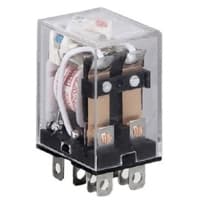
02. Relay:
The most popular relay for automation work is the 8 Pin Relay. The 8-pin relay has a DC or AC coil as the main part. which is connected to two pins. There are two common parts. Underneath a Common part are a NO and an NC part. No part is normally open with a common part and the NC part is normally closed. The timer base used for automation is the same as the 8-relay base. That is, switching can be done using the timer base. This is basically how a relay switch works for the relay.
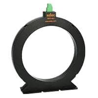
A current Transformer is a device used to measure alternating currents. The transformer used with the ammeter for high-quality AC current measurement is called a current transformer abbreviated as CT. Current transformers are mainly used to measure high current flow. We know that high power lines carry a lot of currents. In this case, an ordinary ammeter or multimeter cannot measure this current flow. Current transformers are used in Acorn.
04. PT Coil:
Instrument transformers Potential Transformers are used to measure high voltages Control system. Potential or voltage transformers are used to measure voltage supply. It is a transformer that is used to step down high voltage to low range. It is used to measure high voltages in circuits with low-range meters. the meter is connected in parallel with the load to measure the voltage supply. The basic principle and operation of a potential transformer are very similar to that of a standard power transformer. The potential transformer is called PTO for short circuits.
Thank You for visiting the website. Keep visiting for more Updates.
Frequently asked questions
Several types of relays can be used in a substation, depending on the specific application and requirements. Some common types of relays used in substations include electromechanical relays, static relays, or microprocessor-based relays.
Protective relays in industrial and utility systems could be used to protect zones within the power supply system. These zones are usually based on functionality such as generators, motors, transformers, distribution feeders and buses, or transmission lines.
Detailed Solution. Buchholz relay is used for the protection of the transformers from the faults occurring inside the transformer. Short circuit diagrams faults such as inter-turn faults, incipient winding faults, or core faults may occur due to the impulse breakdown of the insulating oil and simply the transformer oil.
Transformer protection could be broadly categorized as electrical protection implemented by sensing mainly the current flow through it, but also voltage and frequency, and, as mechanical protection implemented by sensing operational parameters like oil pressure/ level, gas evolved, and oil & winding temperature.
A Buchholz relay was an electrical transformer protection device. For conservator-type electrical transformers, a gas-actuated relay and Buchholz relay are installed between the conservator tank and the main tank. Gas-actuated relays have 2 functions, whereas a Buchholz Relay has three.
Read more Single Phase Wiring
What is a kilowatt-hour (kWh) | kwh formula | What does kwh mean
Introduction to Electrical Units and CircuitskW and kWh on your electricity bill As your home uses electricity during...
What is the Difference Between kVA | What does KVA mean | kVA formula
Difference Between KVA ExplainedWhat does KVA Mean? There are technical terms aplenty when it comes to generators, and...
Power Factor | Power Unit | Energy | Electricity Unit
Power factor definition | Calculating Power FactorPower Factor Values In a purely resistive circuit, the power factor...
0 Comments