Selector Switch in Voltmeter Wiring:
This diagram shows how to make Selector Switch in Voltmeter Wiring. In this circuit, we use a TP MCB ( Tripple Pole Miniature Circuit Breaker ), a selector switch, voltmeter. This circuit is very simple and easy to make. If you want to know more details about this circuit please check our youtube video below the post and stay with us for more updates.
Advertisements
Diagram of Selector Switch in Voltmeter Wiring:

Components needed For this Project:
You can get the components from any of the sites below:
- TP MCB 16A [See Buy Click Amazon]
- Selector Switch (220V AC) [See Buy Click Amazon]
- single phase Volt Meter [See Buy Click Amazon]
*Please note: These are affiliate links. I may make a commission if you buy the components through these links. I would appreciate your support in this way!
Advertisements
Components used to make the Selector Switch in Voltmeter Wiring:
01. TP MCB:

The full meaning of MCB is Miniature Circuit Breaker for TP MCB. MCB is an electromagnetic switch or device. If for any reason a short circuit occurs in the supply line or load line (line to line or line to neutral) or in case of overload MCB. the MCB automatically trips and disconnects the main line circuit or household power supply Connection. TP MCB In 3 Pole MCB, Switching & Protection is affected in only 3-Phases and the Neutral is not part of the MCB. 3 pole MCB signifies the Connection of Three Wires for a 3-Phase system Red-Yellow-Blue Phase. 3-Phase Supply Only Without Neutral.
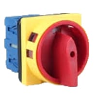
02. Selector Switch:
A Mechanical Switch That can be rotated Left, right, or center to open or close the Electrical contacts is known as a Selector switch. The Main Function of This Selector Switch is to Control Devices and also to Switch Between a Minimum of 2 or Above Electrical Circuits. The Perfect Used for Selector Switch is When Used for Controlling the Output of a Device. We know that a Selector switch is Used to control the electrical current flow in a Circuit it can also be used to both Initiate and inhibit the Current Flow.
03. Volt Meter:

An instrument that measures the potential difference between any two points in a circuit directly in volts is called a voltmeter. A voltmeter is an Electrical instrument that directly measures the potential difference between any 2 points in a circuit in volts. The voltmeter is connected in parallel with the 2 points in the circuit where the potential difference is to be measured. This instrument consists of a galvanometer. Like an electric cell or an ammeter, a voltmeter has 2 terminals, a positive and a negative terminal. Usually, the positive end is red and the negative end is black.
Thank You for visiting the website. Keep visiting for more Updates.
Frequently asked questions
Voltmeter and ammeter selector switches are used to switch between phases for measurement on a 3-phase system. Voltmeter selector switches were available to switch between line-line voltage or line-line and line-neutral voltage while the ammeter selector switch switches between the 3-phase line current diagram.
Selector Knob and Button: Turn this knob or press the button to select your unit of measure. These choices on the display match the choices on the knob. Resistance: This was measured in ohms. On analog multimeters, there's a scale on the display labeled as ohms, resistance, and the ohm symbol (Ω).
A type selector is sometimes referred to as a tag name selector and element selector because it selects an HTML tag or element in your document. Type selectors were not case-sensitive. In the example below, we have used the span, em, and are strong selectors.
It is an instrument used to measure the potential difference across two terminals in a circuit. It can measure the voltage of the order of millivolts to the order of kilovolts. It is connected in parallel to the source across which the voltage is to be measured.
The working formula is given by V = I(full scale)* R(series) + v(full scale). The sensitivity of the voltmeter is the reciprocal of the current at full scale. The smaller the current value, the more accurate and sensitive the voltmeter.
Read more Single Phase Wiring
What is a kilowatt-hour (kWh) | kwh formula | What does kwh mean
Introduction to Electrical Units and CircuitskW and kWh on your electricity bill As your home uses electricity during...
What is the Difference Between kVA | What does KVA mean | kVA formula
Difference Between KVA ExplainedWhat does KVA Mean? There are technical terms aplenty when it comes to generators, and...
Power Factor | Power Unit | Energy | Electricity Unit
Power factor definition | Calculating Power FactorPower Factor Values In a purely resistive circuit, the power factor...
0 Comments