Diagram of Motor protection circuit breaker wiring:
This diagram shows how to make motor protection circuit breaker wiring. In this circuit, we use TP MCB ( Tripple Pole Miniature Circuit Breaker ), an MPCB ( Motor Protection Circuit Breaker ), two indicator lights, and a 3-phase motor. This circuit is very simple and easy to make. If you want to know more details about this circuit please check our youtube video below the post and stay with us for more updates.
Advertisements
Diagram of Motor protection circuit breaker wiring:

Components needed For this Project:
You can get the components from any of the sites below:
- TP MCB 20A [See Buy Click Amazon]
- MPCB Switch [See Buy Click Amazon]
- Indicator Light 220v AC [See Buy Click Amazon]
- 3 Phase Motor (5 HP) [See Buy Click Amazon]
*Please note: These are affiliate links. I may make a commission if you buy the components through these links. I would appreciate your support in this way!
Advertisements
Components used to make the Motor protection circuit breaker wiring:
01. TP MCB:

The full meaning of MCB is Miniature Circuit Breaker for TP MCB. MCB is an electromagnetic switch or device. If for any reason a short circuit occurs in the supply line or load line (line to line or line to neutral) or in case of overload MCB. the MCB automatically trips and disconnects the main line circuit or household power supply Connection. TP MCB In 3 Pole MCB, Switching & Protection is affected in only 3-Phases and the Neutral is not part of the MCB. 3 pole MCB signifies the Connection of Three Wires for a 3-Phase system Red-Yellow-Blue Phase. 3-Phase Supply Only Without Neutral.
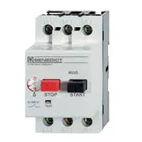
02. MPCB:
MPCB = Motor Protection Circuit Breakers. A protection system against electrical faults, such as short circuits for AC Line 220V. line-to-ground faults, and line-to-line faults. Electrical faults that are below the MPCB is breaking capacity can be interrupted by the board.MCBs are designed for a wide variety of functions circuit protection functions while MPCBs are used for the specific function of protecting circuits driving electric motors.
03. Indicator Light:

An indicator lamp just Sounds Technical, Sometimes it is called a Supervisory light Indicator. Indicator lights are amber in color and can be located at the Front, the Rear, and Sometimes at the Side of the car on both the left And Right-hand sides. The Common colors used by Indicator lamps are red, yellow, blue, white, and green line system. A Panel Indicator Lamp Generally has up to 5 Differently Colored Segments to Indicate Various Conditions on the Machine or Process system.
04. 3 Phase Motor:
A 3-phase electric motor uses a 3-phase Power Supply to Convert Electric Energy into Mechanical Energy. It contains four Wires (Three hot Wires and one Neutral Wire) and Uses 3 Alternating Currents of the Same Frequency. Since it Generates a Rotating Magnetic Field, it does not need a Capacitor for the Startup. Some 3-phase Motors are Reversible, Which Means they can serve as Generators by Turning Mechanical Energy into Electrical Energy.

Thank You for visiting the website. Keep visiting for more Updates.
Frequently asked questions
A Motor Protection Circuit Diagram Breaker is a simple electromechanical device that protects an individual electric motor against overload, fluctuations in input current flow, or unscheduled interruptions to the main circuit diagram This includes line faults and phase loss or imbalance in 3-phase motor
The basic working principle is similar to all other circuit diagram breakers. Thermal protection is used to guard the electric power motor against overload. It was based on an expanding and contracting contact that disconnects the motor if excessive current flow is detected.
An MPCB can protect a motor against overload and short circuits. MCCBs, when used in motor protection circuit diagrams can protect against short circuit diagrams only. Hence additional overload relay and contactor are required. A Motor can be directly turned ON and OFF manually using an MPCB, the contactor is optional.
During the flow of current from one contact to another, the path becomes so heated that it glows in the form of an arc. Arc in circuit breaker. Whenever the contacts of the circuit breaker open while carrying load there is an arc in the medium between the separating contacts of the circuit breaker.
Vacuum circuit diagram breakers were compactly designed for safe operation, high reliability, and easy maintenance, and find a use for various types of high voltage circuits. They interrupt an electric circuit diagram to prevent unwarranted current flow caused by a short-circuit diagram. typically resulting from an overload.
Read more Single Phase Wiring
What is a kilowatt-hour (kWh) | kwh formula | What does kwh mean
Introduction to Electrical Units and CircuitskW and kWh on your electricity bill As your home uses electricity during...
What is the Difference Between kVA | What does KVA mean | kVA formula
Difference Between KVA ExplainedWhat does KVA Mean? There are technical terms aplenty when it comes to generators, and...
Power Factor | Power Unit | Energy | Electricity Unit
Power factor definition | Calculating Power FactorPower Factor Values In a purely resistive circuit, the power factor...
0 Comments