Emergency stop button switch wiring:
This diagram shows how to make an Emergency stop button switch wiring. In this circuit, we use a magnetic contactor, an NO Switch, an NC Switch, an emergency stop switch, and a buzzer. First, we need to connect the contactor to the power source and then connect all switches and buzzers to the contactor. Now this circuit is ready for use. If you want to know more about this circuit, please check our youtube video below the post.
Advertisements
Diagram of Emergency stop button switch wiring:

Components needed For this Project:
You can get the components from any of the sites below:
- Magnetic Contactor 40A [See Buy Click Amazon]
- Emergence Switch [See Buy Click Amazon]
- Alarm Siren [See Buy Click Amazon]
- Push Button NO Switch [See Buy Click Amazon]
- Push Button NC Switch [See Buy Click Amazon]
*Please note: These are affiliate links. I may make a commission if you buy the components through these links. I would appreciate your support in this way!
Advertisements
Components used to make the Emergency stop button switch wiring:
01. Magnetic Contactor:

A magnetic contactor is an electromagnetic switching device. It is generally used for controlling 3-phase Motors. The operation of a magnetic contactor is similar to that of a Relay. but a relay is used for low-power or low-voltage connections, and a magnetic contactor is used for high-power or high-voltage connections. As soon as the supply is applied to the magnetic contactor coil. its normally open contacts are closed and normally closed contacts are opened and the associated devices are also operated. This is how a magnetic contactor works.
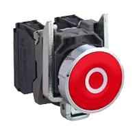
02. Emergency Switch:
An Emergency Stop button, also known as an E-Stop, is for The person using the machinery and is a fail-safe control switch that provides safety both for the machinery. The Purpose of the emergency Push Button is to Stop the Machinery quickly when there is a risk of injury or the Workflow Requires Stopping. All Machinery Requires an Emergency Stop button to Reduce Risk. Buttons are typically red, Often With a Yellow Background to Ensure a Vivid and Easily Identified Solution.
03. Buzzer:
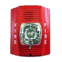
A Siren is a loud noise-making device. Civil Defense Sirens are Mounted in Fixed Locations and Used to Warn of Natural Disasters or Attacks. Sirens are Wsed on Emergency service Vehicles Such as ambulances, Police Cars, And fire Engines. There are 2 General types: Mechanical and Electronic. A civil Defense siren, also known as an air-raid siren or Tornado Siren. is a Siren Used to Provide an Emergency Population Warning to the General Population of Approaching Danger system.
04. NO Switch:
NO (Normally Open) Terms Refer to a Type of Dry Contact or Wet Contact. A Push to Make Switch Allows Electricity to flow Between its 2 contacts when held in. When the button is released, the Circuit is broken. This type of Switch is also known as A Normally Open (NO) Switching system. As its name implies, a Normally Open (NO) Switch Contact or “a Contact” is a Switch. Put very simply, a Normally Open Sensor will have no Current When in a Normal State But When it Enters an Alarm State it will have +5V applied to the Circuit.

05. NC Switch:

An NC (Normally Closed) Push Button is a Push Button That, In Its Default State, Makes Electrical Contact With The Circuit. An NC (Normally Closed) Push Button is a Push Button that, in its Default State, Makes electrical Contact With the Circuit. When The Button Is Pressed Down, The Switch no Longer Makes Electrical Contact And The Circuit is Now Open. When The Button is Not Pressed, Electricity Can Flow, But When it is Pressed The Circuit is Broken. This type Of Switch is Also known As a Normally Closed (NC) Switch.
Thank You for visiting the website. Keep visiting for more Updates.
Frequently asked questions
As a special function button commonly used in industry, the emergency stop button is usually installed in the control panel or button box. Its structure mainly includes 3 parts: actuator, holder, and switching the elements. The actuator is used to operate and release components, usually with a push rod and spring to achieve action.
An emergency stop push button switch was used as a safety measure to stop hazardous parts (loads). An Emergency Stop Switch is more highly visible in color and shape and easier to operate in emergency situations.
The largest difference is the purpose of the two buttons. A general push button is used for normal operation of the machine – for example turning it on and off. Whereas an emergency stop button is used in the event of an emergency to immediately stop the machine to attempt to resolve the emergency.
The emergency stop shall be made as per stop category 0 or 1 as described above in this document. 1. If there is a possibility of hazards or damage due to the electrical power supply, emergency switching off should be provided.
An emergency stop push button is a safety device that is often used on heavy-duty machinery and other devices within the industrial sector. They were an important feature for the devices because when they were compressed, the power supply to the device was immediately cut.
Read more Single Phase Wiring
What is a kilowatt-hour (kWh) | kwh formula | What does kwh mean
Introduction to Electrical Units and CircuitskW and kWh on your electricity bill As your home uses electricity during...
What is the Difference Between kVA | What does KVA mean | kVA formula
Difference Between KVA ExplainedWhat does KVA Mean? There are technical terms aplenty when it comes to generators, and...
Power Factor | Power Unit | Energy | Electricity Unit
Power factor definition | Calculating Power FactorPower Factor Values In a purely resistive circuit, the power factor...
0 Comments