Submersible Pump Wiring Diagram:
This diagram shows how to make Submersible Pump Wiring Diagram. In this circuit, we use a DP MCB ( Double Pole Miniature Circuit Breaker ), an overload switch, a switch, a capacitor, a single-phase submersible water pump, an indicator light, a magnetic contactor, and a wire connector. This circuit is very simple and easy to make. If you want to know more about this circuit please stay check our youtube video for clear details.
Advertisements
Diagram of Submersible Pump Wiring:

Components needed For this Project:
You can get the components from any of the sites below:
- DP MCB 16A [See Buy Click Amazon]
- Magnetic Contactor 25A [See Buy Click Amazon]
- Overload switch [See Buy Click Amazon]
- SPST Switch [See Buy Click Amazon]
- Board Indicator [See Buy Click Amazon]
- Terminal Block [See Buy Click Amazon]
- 50 MFD Capacitor (220V ac Line) [See Buy Click Amazon]
- single phase Submersible water pump (1 HP) [See Buy Click Amazon]
*Please note: These are affiliate links. I may make a commission if you buy the components through these links. I would appreciate your support in this way!
Advertisements
Components used to make the Submersible Pump Wiring Diagram:
01. DP MCB:

DP MCB In 2 Pole MCB, switching & protection is affected in phases and the neutral. A Double Pole or DP Switch is a Switch that Controls 2 Circuits at the same time. In terms of Residential Switching, this Normally means it Switches the live and Neutral at the same time. In Layperson Terms, Double Pole switches or DP Switches are Exclusively Designed to Control 2 Different Electrical Circuits at the same time, which allows the Appliances to Isolate safely and reliably. Fan or light Combinations and Medical Equipment are some of the many applications for DP Electrical Switches and Electrical components.
02. Magnetic Contactor:
A magnetic contactor is an electromagnetic switching device. It is generally used for controlling 3-phase Motors. The operation of a magnetic contactor is similar to that of a Relay. but a relay is used for low-power or low-voltage connections, and a magnetic contactor is used for high-power or high-voltage connections. As soon as the supply is applied to the magnetic contactor coil. its normally open contacts are closed and normally closed contacts are opened and the associated devices are also operated. This is how a magnetic contactor works.

03. Overload:
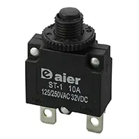
An overload relay is a safety device that protects your circuit diagram against damage caused by high-power loads. The relay opens if the load exceeds a certain amount. protecting the circuit from destruction. The simplest version of an overload relay is a single-pole, single-throw (SPST) switch. An overload relay is also referred to as a relay switch. switch is a device that opens the circuit in the event of an electrical, thermal, or power overload system. When mounted with a contactor they create a motor starter connection.
04. Switch:
An SPST (Single Pole Single Throw) Switch is a Switch That only Has a Single Input and can Connect Only to one Output. This means it Only Has one Input Terminal and Only 1 Output Terminal. A Switch is a Mechanical or Controlling Device That Changes the Flow of Current Direction or Interrupts the Flow of Current Within a Circuit diagram. An electrical line using Single Pole Single Throws (SPST) is Perfect for on-off switching. When the SPST is closed, the Circuit is Closed and the light from the lamp switches on the system. When The Single Pole Single Throw (SPST) is then opened, the light from the lamp goes out and the Circuit is off.

05. Indicator:

An indicator lamp just Sounds Technical, Sometimes it is called a Supervisory light Indicator. Indicator lights are amber in color and can be located at the Front, the Rear, and Sometimes at the Side of the car on both the left And Right-hand sides. The Common colors used by Indicator lamps are red, yellow, blue, white, and green line system. A Panel Indicator Lamp Generally has up to 5 Differently Colored Segments to Indicate Various Conditions on the Machine or Process system.
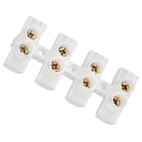
06. Wire Connector:
Terminal Clocks are Connectors That Terminate a Single wire and Connect it to a circuit or other system. Terminal Blocks come in a range of shapes, Sizes, and ratings, but Always Terminate a single Wire and are Never multi-pole. Terminal Blocks are used to Secure or Terminate Wires and, in Their Simplest form, Consist of Several Individual Terminals Arranged in a long strip system. Terminals are Useful for Connecting the Wiring to the GND or, in the Case of Electrical power, for Connecting Electrical Switches and Outlets to the Mains side.
07. Capacitor:
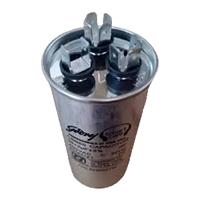
Motor Starting Capacitors are used during the Motor Startup Phase and are Disconnected From the Circuit once the Rotor Reaches a Predetermined Speed, Which is Usually about 75% of the Maximum Speed for that Motor type. These Capacitor Usually Have Capacitance Values Of Over 70 UF. The Starting capacitor creates a Current-to-Voltage lag in the Separate start Windings of the Motor. Starting Capacitor are Wired into The Auxiliary Winding Circuit of the Motor and are Disconnected from the main winding circuit by the Centrifugal Switch once the Motor has Reached a Predetermined Speed.
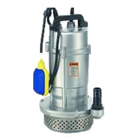
08. Submersible Pump:
A Submersible Pump Is an Air-Tight Sealed Motor Close-Coupled to The pump is body. The Main Advantage of This Type of Pump is That it Prevents Pump Cavitation, a Problem Associated With a High Elevation Difference Between the submersible Pump and the Fluid Surface. Submersible Pumps As The Name Suggests Are made To Be fully Submerged in Water. It is a Centrifugal Water Pump, Meaning It Has a Motor That Powers An impeller Designed to Rotate And Push Water Outwards. The Motor is located Within a Waterproof Seal and is Closely Coupled to The body of The Pump That it Powers.
Thank You for visiting the website. Keep visiting for more Updates.
Frequently asked questions
Submersible pump wire is typically used to supply electricity to wells, sump pumps, and large-scale pumping systems in residential, farming, or industrial applications. Flat Submersible Pump Wire. Twisted Submersible Pump Wire.
Residential Capacity Based on Fixture Count. The capacity of the motor system in gallons per minute should equal the number of fixtures in the home. This must take into account all uses for the kitchen, bath, appliances, outside irrigation, pool, and special fixtures, such as a hot tub.
This week we will be talking about the difference between two and three-wire submersible well pumps. Firstly, both types feature a ground wire which should not be counted. Two wire pumps will have two black wires and a green wire. Three wire pumps have black, red, yellow, or green wires.
In North America, the small ones (1/3-hp, 1/2-hp, 3/4-hp) are usually 120V AC. Larger ones are 240V AC. Much larger ones (over 5 to 10 hp) are three-phase (240, 277, 460, etc). Most everywhere else, all pumps (like all electric motors) are 240v AC until they get over about 10 kW and then they'll be three-phase.
Submersible pumps are used to motor out water to a minimum depth of 15 cm or from open water to supply an incident ground with water. Submersible pumps could be lowered into a subway or down a cliff into open water and still operate.
Read more Single Phase Wiring
What is a kilowatt-hour (kWh) | kwh formula | What does kwh mean
Introduction to Electrical Units and CircuitskW and kWh on your electricity bill As your home uses electricity during...
What is the Difference Between kVA | What does KVA mean | kVA formula
Difference Between KVA ExplainedWhat does KVA Mean? There are technical terms aplenty when it comes to generators, and...
Power Factor | Power Unit | Energy | Electricity Unit
Power factor definition | Calculating Power FactorPower Factor Values In a purely resistive circuit, the power factor...
0 Comments