Timer and contactor wiring diagram:
This diagram shows how to make Timer and contactor wiring diagram. In this circuit, we use an RCCB ( Residual Current Circuit Breaker ), an RCBO ( Residual Current Breaker with Over-Current ), a magnetic contactor, and a timer. First, we need to connect the RCCB with the power source, then connect the RCBO, then connect the contactor with the RCBO, then connect the timer with the circuit.
Advertisements
Diagram of Timer and contactor wiring:

Components needed For this Project:
You can get the components from any of the sites below:
- DP RCCB 32A [See Buy Click Amazon]
- DP RCBO 20A [See Buy Click Amazon]
- Magnetic Contactor 25A [See Buy Click Amazon]
- 8 Pin Timer 220V AC [See Buy Click Amazon]
*Please note: These are affiliate links. I may make a commission if you buy the components through these links. I would appreciate your support in this way!
Advertisements
Components used to make the Timer and contactor wiring diagram:
01. RCCB:
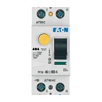
The Residual Current Circuit breaker RCCB is the Safest device to detect and Trip against Electrical Leakage current. This ensures protection against Electric shock Caused by indirect contact. Circuit breakers (CB) are automatically Operated Electrical Switches that Protect Electrical Circuits from Short-Circuiting or Overloading systems. It Protects against many major accidents. RCCB Circuit Breaker is an Electrical Wiring device whose function is to disconnect the current in the circuit.
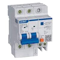
02. RCBO:
An RCBO protects Electrical equipment against 2 types of faults. Residual current and over current. Residual current. or earth leakage as it is sometimes referred to, occurs when there is a break in the circuit which can be caused by faulty electrical wiring or if the wire is accidentally cut. When there is a break in the circuit which may be due to faulty electrical wiring or accidental cutting of the wire. To prevent the current from being redirected and causing an electric shock. the RCBO current breaker stops it.
03. Magnetic Contactor:

A magnetic contactor is an electromagnetic switching device. It is generally used for controlling 3-phase Motors. The operation of a magnetic contactor is similar to that of a Relay. but a relay is used for low-power or low-voltage connections, and a magnetic contactor is used for high-power or high-voltage connections. As soon as the supply is applied to the magnetic contactor coil. its normally open contacts are closed and normally closed contacts are opened and the associated devices are also operated. This is how a magnetic contactor works.
04. Timer:
A timer is a type of time-switching device that controls and controls Electrical circuits and electrical and electronic devices through time setting (on/off). The timer is basically 8-pin. Like other controlling devices the timer has a coil and when this coil is magnetized, the timer works on/off. The timer has 2 common ends and each common end has normally close and normally open options. When the timer is set by time, the timer trips at the end of that time and turns the common is normally closed (on) to open (off) and normally open (off) to close (on). This is how the timer works.

Thank You for visiting the website. Keep visiting for more Updates.
Frequently asked questions
We use a contactor to turn on and off heavy and the high voltage electrical devices such as motors, fans, pumps, etc. – The reason that we used a contactor was to control these heavy high voltage electrical devices indirectly and safely via a PLC and not to connect the PLC directly to these output devices.
Contactors are designed to handle high-current diagram loads, while relays are suitable for low to medium-current flow loads. This difference in load capacity results from the design and construction of the devices, with contactors featuring larger and more robust auxiliary contacts to accommodate higher currents diagram.
In short, the contactor belongs to the main circuit element, and its task is to control the on-off of the main circuit diagram. The relay is an auxiliary circuit diagram component, and its task is to perform signal transmission and control the main circuit diagram components.
Electromagnetism was the timer relay working principle. One relay coil was always on, while the other could be turned off and on with an electric signal sent through it from a control device such as a phone or the computer system.
An electronic contactor is a simple switching device, whereas the circuit diagram breaker is a protective system. The primary function of the contactor is controlling the power supply. A circuit diagram breaker does the protecting. The contractor works under normal situations.
Read more Single Phase Wiring
What is a kilowatt-hour (kWh) | kwh formula | What does kwh mean
Introduction to Electrical Units and CircuitskW and kWh on your electricity bill As your home uses electricity during...
What is the Difference Between kVA | What does KVA mean | kVA formula
Difference Between KVA ExplainedWhat does KVA Mean? There are technical terms aplenty when it comes to generators, and...
Power Factor | Power Unit | Energy | Electricity Unit
Power factor definition | Calculating Power FactorPower Factor Values In a purely resistive circuit, the power factor...
0 Comments