Timer contactor wiring diagram:
This diagram shows how to make Timer contactor wiring diagram. In this circuit, we use a DP MCB ( Double Pole Minature Circuit Breaker ), a magnetic contactor, a timer, 3 switches, and 3 tube lights. First, we need to connect the DP MCB with the power source, then connect the contactor with the timer and switch, and light.
Advertisements
Diagram of Timer contactor wiring:

Components needed For this Project:
You can get the components from any of the sites below:
- DP MCB 20A [See Buy Click Amazon]
- Magnetic Contactor 25A [See Buy Click Amazon]
- 8 Pin Timer 220V AC [See Buy Click Amazon]
- Fluorescent Tube [See Buy Click Amazon]
- 2 way switch [See Buy Click Amazon]
*Please note: These are affiliate links. I may make a commission if you buy the components through these links. I would appreciate your support in this way!
Advertisements
Components used to make the Timer contactor wiring diagram:
01. DP MCB:

DP MCB In 2 Pole MCB, switching & protection is affected in phases and the neutral. A Double Pole or DP Switch is a Switch that Controls 2 Circuits at the same time. In terms of Residential Switching, this Normally means it Switches the live and Neutral at the same time. In Layperson Terms, Double Pole switches or DP Switches are Exclusively Designed to Control 2 Different Electrical Circuits at the same time, which allows the Appliances to Isolate safely and reliably. Fan or light Combinations and Medical Equipment are some of the many applications for DP Electrical Switches and Electrical components.
02. Magnetic Contactor:
A magnetic contactor is an electromagnetic switching device. It is generally used for controlling 3-phase Motors. The operation of a magnetic contactor is similar to that of a Relay. but a relay is used for low-power or low-voltage connections, and a magnetic contactor is used for high-power or high-voltage connections. As soon as the supply is applied to the magnetic contactor coil. its normally open contacts are closed and normally closed contacts are opened and the associated devices are also operated. This is how a magnetic contactor works.

03. Timer:

A timer is a type of time-switching device that controls and controls Electrical circuits and electrical and electronic devices through time setting (on/off). The timer is basically 8-pin. Like other controlling devices the timer has a coil and when this coil is magnetized, the timer works on/off. The timer has 2 common ends and each common end has normally close and normally open options. When the timer is set by time, the timer trips at the end of that time and turns the common is normally closed (on) to open (off) and normally open (off) to close (on). This is how the timer works.
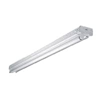
04. Tube Light:
The structural element of the tube light is an airtight glass tube which is commonly called a sealed glass tube. This tube is airtight. The tube fills with a small amount of mercury. Also contains an inert gas (usually argon). The tube inside is also coated with phosphorus. That is why it looks white. There are 2 electrodes at both ends of the tube which can create an electric field between them. These 2 electrodes are again connected to an electrical circuit. Electrical This circuit usually consists of a starter switch and ballast. This circuit is connected to our AC supply. The difference between ordinary incandescent bulbs and fluorescent bulbs (which we call tube lights) is the process of activating or exciting the atoms. In normal bulbs, the atoms are activated by heating. In fluorescent bulbs. this is done through accelerated chemical reactions.
05. 2 -Way Switch:
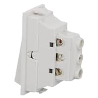
The 2-Way Switch has a wire connection system. It is a type of switch that has three wire connections. And it really has no off or on. Both sides can be turned on or off depending on how you connect one to the other. The connection of the two-way switch is different. If you use it as a changer, then put the load in the middle one and two separate lines in the upper and lower ones. The two-way switch is a type of multiway switch. Multiway switches have more points and can be controlled in multiple ways simultaneously.
Thank You for visiting the website. Keep visiting for more Updates.
Read more Single Phase Wiring
What is a kilowatt-hour (kWh) | kwh formula | What does kwh mean
Introduction to Electrical Units and CircuitskW and kWh on your electricity bill As your home uses electricity during...
What is the Difference Between kVA | What does KVA mean | kVA formula
Difference Between KVA ExplainedWhat does KVA Mean? There are technical terms aplenty when it comes to generators, and...
Power Factor | Power Unit | Energy | Electricity Unit
Power factor definition | Calculating Power FactorPower Factor Values In a purely resistive circuit, the power factor...
0 Comments