3 Phase Distribution Board Wiring:
This diagram shows how to make 3 Phase Distribution Board Wiring. In this circuit diagram, we use an ampere meter, voltage signal light, some MCB circuit breakers, ct coil, and MCCB circuit breaker, etc. This diagram is very easy to connect, if you want to know more about this diagram please check our youtube video for more information.
Advertisements
Diagram of 3 Phase Distribution Board Wiring:

Components needed For this Project:
You can get the components from any of the sites below:
- MCCB 100A [See Buy Click Amazon]
- CT Transformer [See Buy Click Amazon]
- Single Phase Amperemeter [See Buy Click Amazon]
- single phase Volt Meter [See Buy Click Amazon]
- Indicator Light 220v AC [See Buy Click Amazon]
*Please note: These are affiliate links. I may make a commission if you buy the components through these links. I would appreciate your support in this way!
Advertisements
Components used to make the 3 Phase Distribution Board Wiring:
01. MCCB:
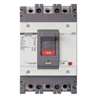
The MCCB consists of a bimetallic sheet that expands and contracts when the temperature of the MCCB changes. Due to overload, the bimetallic strip will start to bend and eventually. it will trip if more current flows in the circuit than the predetermined current. The trip mechanism opens the breaker. MCCB stands for Molded Case Circuit Breaker. It is another type of electrical protection device that is used when the load current exceeds the limit of a miniature circuit breaker. The MCCB provides Protection against Overload, and Short Circuit Faults and is also used for Switching the Circuits.
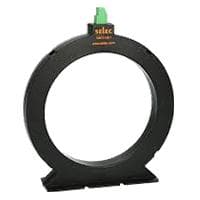
02. CT Coil:
A current Transformer is a device used to measure alternating currents. The transformer used with the ammeter for high-quality AC current measurement is called a current transformer abbreviated as CT. Current transformers are mainly used to measure high current flow. We know that high power lines carry a lot of currents. In this case, an ordinary ammeter or multimeter cannot measure this current flow. Current transformers are used in Acorn.
03. Ampere Meter:

Ammeter, an instrument, with the help of which the flow of electricity can be measured directly in Electrical units, amperes. It is a galvanometer with very low resistance. As a result, the entire current flows through the meter coil. Current is measured with an ammeter. So it can be said that the device that measures the flow of current in an ampere unit is an ammeter. Electric current is the flow of electrons whose unit is an ammeter. So it can be said that the device that measures the flow of current in an ampere unit is an ammeter. An ideal ammeter has no internal resistance. But in reality. the ammeter has little internal resistance. The range of the ammeter depends on this resistance.
04. Voltage Meter:
An instrument that measures the potential difference between any two points in a circuit directly in volts is called a voltmeter. A voltmeter is an Electrical instrument that directly measures the potential difference between any 2 points in a circuit in volts. The voltmeter is connected in parallel with the 2 points in the circuit where the potential difference is to be measured. This instrument consists of a galvanometer. Like an electric cell or an ammeter, a voltmeter has 2 terminals, a positive and a negative terminal. Usually, the positive end is red and the negative end is black.

05. Signal Light:

An indicator lamp just Sounds Technical, Sometimes it is called a Supervisory light Indicator. Indicator lights are amber in color and can be located at the Front, the Rear, and Sometimes at the Side of the car on both the left And Right-hand sides. The Common colors used by Indicator lamps are red, yellow, blue, white, and green line system. A Panel Indicator Lamp Generally has up to 5 Differently Colored Segments to Indicate Various Conditions on the Machine or Process system.
Thank You for visiting the website. Keep visiting for more Updates.
Frequently asked questions
Three-phase distribution boards are panels that house the circuit diagram breakers, ground leakage protection units, and fuses that are used to distribute power supply to individual consumer points or circuit diagrams within a building.
A 3-phase charge point uses 3 400 V (power current) and has 16 A or 32 A current flow per power socket. So, the maximum charging capacity per power supply socket is 22 kW (with 16 A, you get 11 kW). If you do not have a 3 -3-phase connection, you could usually request an extension from the grid operator.
An electrical distribution board (or panel board) is a component of an electricity supply system that divides an electrical power feed into subsidiary circuits, while providing a protective fuse or circuit diagram breaker for each circuit diagram, in a common enclosure.
A distribution board was also called a panel board, breaker panel, electric panel, or DB box. Its main function was to divide the electrical power supply evenly among all the electrical devices. The primary functions also include power supply generation, transmission, and distribution.
In addition to circuit diagram breakers, distribution boards also contain a variety of other components, such as fuses, switches, and surge protectors. These components work together to ensure that the electrical power supply is distributed safely and efficiently.
Read more Single Phase Wiring
What is a kilowatt-hour (kWh) | kwh formula | What does kwh mean
Introduction to Electrical Units and CircuitskW and kWh on your electricity bill As your home uses electricity during...
What is the Difference Between kVA | What does KVA mean | kVA formula
Difference Between KVA ExplainedWhat does KVA Mean? There are technical terms aplenty when it comes to generators, and...
Power Factor | Power Unit | Energy | Electricity Unit
Power factor definition | Calculating Power FactorPower Factor Values In a purely resistive circuit, the power factor...
0 Comments