3 phase motor ampere meter calculation diagram:
This diagram shows how to make 3 phase motor ampere meter calculation diagram. In this circuit, we use FP MCB ( Four Pole Minature Circuit Breaker ), a magnetic contactor, an overload, an ampere meter, and a selector switch. First, we need to connect FP MCB with the power source, then connect the magnetic contactor and overload with the FP MCB, then connect the amperemeter and selector switch with the contactor.
Advertisements
3 phase motor ampere meter calculation diagram:

Components needed For this Project:
You can get the components from any of the sites below:
- FT MCB 30A [See Buy Click Amazon]
- Single Phase Amperemeter [See Buy Click Amazon]
- Selector Switch (220V AC) [See Buy Click Amazon]
- Magnetic Contactor 40A [See Buy Click Amazon]
- Motor Protector Overload [See Buy Click Amazon]
*Please note: These are affiliate links. I may make a commission if you buy the components through these links. I would appreciate your support in this way!
Advertisements
Components used to make the 3 phase motor ampere meter calculation diagram:
01. FP MCB:
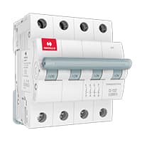
4 pole MCB for 4-Wires Connections, the one additional 4th pole for Neutral Wire Connection so that between Neutral and any of the other three will supply. In 4-Pole MCB the Neutral Pole is also having Protective release as in the Phase Poles connection. 3 Phase Supply with Neutral. TPN means triple pole TP + Neutral which is 3 - phases and Neutral. but the Protection is given for 3 Phases only and in 4 poles MCB Protection is given to all 3-Phases as well as Neutral. In the case of a 4-pole MCB. A Purpose is not to protect the Neutral but it is rather to Isolate the Neutral.
02. Ammeter:
Ammeter, an instrument, with the help of which the flow of electricity can be measured directly in Electrical units, amperes. It is a galvanometer with very low resistance. As a result, the entire current flows through the meter coil. Current is measured with an ammeter. So it can be said that the device that measures the flow of current in an ampere unit is an ammeter. Electric current is the flow of electrons whose unit is an ammeter. So it can be said that the device that measures the flow of current in an ampere unit is an ammeter. An ideal ammeter has no internal resistance. But in reality. the ammeter has little internal resistance. The range of the ammeter depends on this resistance.

03. Selector Switch:
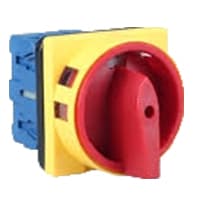
A Mechanical Switch That can be rotated Left, right, or center to open or close the Electrical contacts is known as a Selector switch. The Main Function of This Selector Switch is to Control Devices and also to Switch Between a Minimum of 2 or Above Electrical Circuits. The Perfect Used for Selector Switch is When Used for Controlling the Output of a Device. We know that a Selector switch is Used to control the electrical current flow in a Circuit it can also be used to both Initiate and inhibit the Current Flow.
04. Magnetic Contactor:
A magnetic contactor is an electromagnetic switching device. It is generally used for controlling 3-phase Motors. The operation of a magnetic contactor is similar to that of a Relay. but a relay is used for low-power or low-voltage connections, and a magnetic contactor is used for high-power or high-voltage connections. As soon as the supply is applied to the magnetic contactor coil. its normally open contacts are closed and normally closed contacts are opened and the associated devices are also operated. This is how a magnetic contactor works.

05. Overload Relay:

Overload Protection is Protection Against a Running Overcurrent That Would Cause Overheating of The Protected Equipment. Hence, An Overload is Also a Type of Overcurrent flow. Overload Protection Typically Operates on an Inverse Time curve where the Tripping Time Becomes less as the Current Increases. This Overload Protector is an Essential Component for Many Sockets Power Systems. The Top-Quality Overload Protector can Effectively Protect Electrical Products from Power Surges.
Thank You for visiting the website. Keep visiting for more Updates.
Frequently asked questions
To calculate 3 phase kWh from measuring amps on each phase Use this formula; KW= (volts(avg) x amps(avg) x power supply. factor x 1.732) divided by 1,000. If you don't have a power supply factor use 0.9. Also make sure you use the larger voltage of the system voltages, ex) if it's 480 or 277 use 480 in the formula.
A 3-phase smart meter is different from a single-phase meter in that it measures the power supply you use and notifies you when there is an outage. It can tell you how much power supply your neighbors are using, as well as how much electricity they are using overall.
3-phase meters are usually only necessary for larger industrial and commercial businesses that use a lot more electricity. A 3-phase meter has 3 wires with 3 alternating currents (AC) supplying the meter and site, so much more power supply can be used.
The formula is volts times the square root of 3, which happens to be rounded off to 1.732. For 2 lines each carrying 120 volts, the calculation for this is 120 volts times 1.732, and the result is rounded up to 208 volts. That's why we call it a 208-volt three-phase circuit, or a 208-volt 3 phase line.
If we consider a 120-volt, three-phase circuit diagram, and each phase supports 20 amps, the formula works out to 120 Volts x 20 Amps x 1.732 = 4,157 watts. This is how three-phase can deliver nearly twice the power of single-phase systems.
Read more Single Phase Wiring
What is a kilowatt-hour (kWh) | kwh formula | What does kwh mean
Introduction to Electrical Units and CircuitskW and kWh on your electricity bill As your home uses electricity during...
What is the Difference Between kVA | What does KVA mean | kVA formula
Difference Between KVA ExplainedWhat does KVA Mean? There are technical terms aplenty when it comes to generators, and...
Power Factor | Power Unit | Energy | Electricity Unit
Power factor definition | Calculating Power FactorPower Factor Values In a purely resistive circuit, the power factor...
0 Comments