How to make 3 pole socket connection:
This diagram shows How to make a 3-pole socket connection. In this circuit, we use 3 pin socket, a wire ( NPN Sensor ), and an emergency stop switch. First, we need to connect the power socket to the power source, then connect the wire sensor to the power sockets, then connect the emergency switch to the power sockets. Now this circuit is ready for use.
Advertisements
Diagram of How to make 3 pole socket connection:

Components needed For this Project:
You can get the components from any of the sites below:
- Gang Socket [See Buy Click Amazon]
- Proximity Sensor [See Buy Click Amazon]
- Emergence Switch [See Buy Click Amazon]
*Please note: These are affiliate links. I may make a commission if you buy the components through these links. I would appreciate your support in this way!
Advertisements
Components used to make the How to make 3 pole socket connection:
01. 3-Pin Socket:
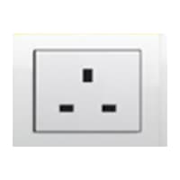
A Power Socket is a Device to Which Electrical Devices Can Be Connected to Receive the Electric Current Required For Their Operation. Connected by a System of Cables to a Power Source, Usually, an Electricity Generation Facility operated by an energy Production company, generally has no moving parts. Instead, it contains metal strips that make contact with the prongs of an Electric plug inserted into the socket. It is Through these Contacts That the Electric current is Transmitted. Electrical Devices that connect to a Power Source Through a Power Socket are Considered to be Portable Because they can easily be Connected and Disconnected From the Power Source.
02. Wire Sensor:
Negative-Positive-Negative (NPN) Proximity Sensors Provide an Active LOW Output. This Means That When an Object Enters the Detecting range of the sensor, the output of the sensor is connected to the ground. This type of sensor is also known as the Sinking sensor. Negative-Positive-Negative and PNP stands for Positive-Negative-Positive Transistors. Negative-Positive-Negative (NPN) Proximity Sensor NPN is Powered on When Enough Current is Supplied From the Transistor base to the Emitter.

03. Emergency Switch:
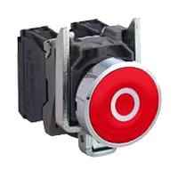
An Emergency Stop button, also known as an E-Stop, is for The person using the machinery and is a fail-safe control switch that provides safety both for the machinery. The Purpose of the emergency Push Button is to Stop the Machinery quickly when there is a risk of injury or the Workflow Requires Stopping. All Machinery Requires an Emergency Stop button to Reduce Risk. Buttons are typically red, Often With a Yellow Background to Ensure a Vivid and Easily Identified Solution.
Thank You for visiting the website. Keep visiting for more Updates.
Frequently asked questions
With a 3-phase power supply connection, you get three individual electric services. So, Every leg of the current supply can reach maximum voltage and gets separated by one-third of the time completed within one cycle. In short, the voltage from a 3-phase power supply connection remains constant.
The three-phase power supply is generated by spinning a magnet inside 3 separate independent coils of wire. Each phase wire of a three-phase distribution line is connected to one of the coils. The 3 separate independent coils of wire produce 3 separate independent voltages with different timing, as shown here.
Phase Conversion is the process of converting single-phase power into three-phase power. A “phase converter” creates a third line of voltage (a 3rd sine wave) allowing a three-phase power supply to be possible in a single-phase environment.
A domestic property would typically require an upgrade from single-phase to three-phase due to a flat conversion, or an increase of the large electrical appliances or facilities, such as a water and heat pump, a stair lift, or an at-home EV charger.
A three-phase inverter (VSI) is operated to control the voltage and its frequency, balance, and leveling of loads, and harmonics mitigation at PCC. To maintain a constant frequency, the VSI is forced to operate at the desired frequency.
Read more Single Phase Wiring
What is a kilowatt-hour (kWh) | kwh formula | What does kwh mean
Introduction to Electrical Units and CircuitskW and kWh on your electricity bill As your home uses electricity during...
What is the Difference Between kVA | What does KVA mean | kVA formula
Difference Between KVA ExplainedWhat does KVA Mean? There are technical terms aplenty when it comes to generators, and...
Power Factor | Power Unit | Energy | Electricity Unit
Power factor definition | Calculating Power FactorPower Factor Values In a purely resistive circuit, the power factor...
0 Comments