3 phase motor starter wiring:
This diagram shows how to make Three phase motor starter wiring diagram. In this circuit, we use a Differential switch, an FP MCB ( Four Pole Minature Circuit Breaker ), an RCCB ( Residual Current Circuit Breaker ), a DP MCB ( Double Pole Minature Circuit Breaker ), a motor protector device, a magnetic contactor, and a timer. First, we need to connect the differential switch with the power source, then connect the FP MCB with the differential switch, then connect the RCCB and DP MCB like in our diagram, then connect the motor protector device, and contactor, then connect the timer with the contactor like our diagram. Now this circuit is ready for use.
Advertisements
Diagram of 3 phase motor starter wiring:

Components needed For this Project:
You can get the components from any of the sites below:
- DP RCBO 40A [See Buy Click Amazon]
- FT MCB 30A [See Buy Click Amazon]
- DP RCCB 32A [See Buy Click Amazon]
- DP MCB 32A [See Buy Click Amazon]
- MPCB Switch [See Buy Click Amazon]
- Magnetic Contactor 40A [See Buy Click Amazon]
- 8 Pin Timer 220V AC [See Buy Click Amazon]
*Please note: These are affiliate links. I may make a commission if you buy the components through these links. I would appreciate your support in this way!
Advertisements
Components used to make the 3 phase motor starter wiring:
01. Differential Switch:
The Residual Current Circuit breaker RCCB is the Safest device to detect and Trip against Electrical Leakage current. This ensures protection against Electric shock Caused by indirect contact. Circuit breakers (CB) are automatically Operated Electrical Switches that Protect Electrical Circuits from Short-Circuiting or Overloading systems. It Protects against many major accidents. RCCB Circuit Breaker is an Electrical Wiring device whose function is to disconnect the current in the circuit.
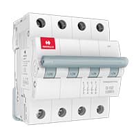
02. FP MCB:
4 pole MCB for 4-Wires Connections, the one additional 4th pole for Neutral Wire Connection so that between Neutral and any of the other three will supply. In 4-Pole MCB the Neutral Pole is also having Protective release as in the Phase Poles connection. 3 Phase Supply with Neutral. TPN means triple pole TP + Neutral which is 3 - phases and Neutral. but the Protection is given for 3 Phases only and in 4 poles MCB Protection is given to all 3-Phases as well as Neutral. In the case of a 4-pole MCB. A Purpose is not to protect the Neutral but it is rather to Isolate the Neutral.
03. RCCB:
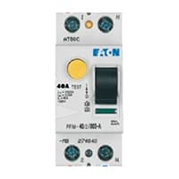
The Residual Current Circuit breaker RCCB is the Safest device to detect and Trip against Electrical Leakage current. This ensures protection against Electric shock Caused by indirect contact. Circuit breakers (CB) are automatically Operated Electrical Switches that Protect Electrical Circuits from Short-Circuiting or Overloading systems. It Protects against many major accidents. RCCB Circuit Breaker is an Electrical Wiring device whose function is to disconnect the current in the circuit.
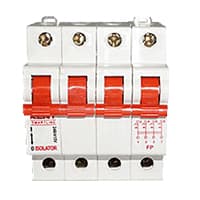
04. DP MCB:
DP MCB In 2 Pole MCB, switching & protection is affected in phases and the neutral. A Double Pole or DP Switch is a Switch that Controls 2 Circuits at the same time. In terms of Residential Switching, this Normally means it Switches the live and Neutral at the same time. In Layperson Terms, Double Pole switches or DP Switches are Exclusively Designed to Control 2 Different Electrical Circuits at the same time, which allows the Appliances to Isolate safely and reliably. Fan or light Combinations and Medical Equipment are some of the many applications for DP Electrical Switches and Electrical components.

05. Motor Protector:
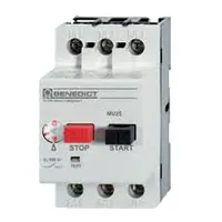
MPCB = Motor Protection Circuit Breakers. A protection system against electrical faults, such as short circuits for AC Line 220V. line-to-ground faults, and line-to-line faults. Electrical faults that are below the MPCB is breaking capacity can be interrupted by the board.MCBs are designed for a wide variety of functions circuit protection functions while MPCBs are used for the specific function of protecting circuits driving electric motors.
06. Magnetic Contactor:
A magnetic contactor is an electromagnetic switching device. It is generally used for controlling 3-phase Motors. The operation of a magnetic contactor is similar to that of a Relay. but a relay is used for low-power or low-voltage connections, and a magnetic contactor is used for high-power or high-voltage connections. As soon as the supply is applied to the magnetic contactor coil. its normally open contacts are closed and normally closed contacts are opened and the associated devices are also operated. This is how a magnetic contactor works.

07. Timer:

A timer is a type of time-switching device that controls and controls Electrical circuits and electrical and electronic devices through time setting (on/off). The timer is basically 8-pin. Like other controlling devices the timer has a coil and when this coil is magnetized, the timer works on/off. The timer has 2 common ends and each common end has normally close and normally open options. When the timer is set by time, the timer trips at the end of that time and turns the common is normally closed (on) to open (off) and normally open (off) to close (on). This is how the timer works.
Thank You for visiting the website. Keep visiting for more Updates.
Frequently asked questions
The six wires are usually labeled U1, U2, V1, V2, W1, and W2. To connect the motor in a Wye configuration, you would connect U1, V1, and W1 together at one end of the motor, and then connect U2, V2, and W2 together at the other end. The remaining ends of U2, V1, and W2 would be used as the three-phase power inputs.
The most common types of three-phase motors are unpacked from their boxes with nine wires needing to be connected from the box on the side. This is typical of motors that could be connected for high or low voltage, or they may be either arranged with Wye or Delta internal connections.
Starter required for 3 phase induction motor because when we start motor high excessive current is produced. The high current will cause the motor windings and it will be burn winding. The function of a starter is to limit the high starting current.
In 3-phase power, the voltage on each wire is 120 degrees phase shifted relative to each of the other wires. Because it is an AC system it allows the voltages to be easily stepped up using transformers to high voltage for transmission or back down for distribution, giving high efficiency.
L1, L2, or L3 coils are live wires with each on their own phase carrying their own phase voltage and phase current flow. Two phases joining together form one line carrying a common line voltage and line current. L1 or L2 phase voltages create the L1/L2 line voltage. The L2 and L3 phases of the voltages create the L2/L3 line voltage.
Read more Single Phase Wiring
What is a kilowatt-hour (kWh) | kwh formula | What does kwh mean
Introduction to Electrical Units and CircuitskW and kWh on your electricity bill As your home uses electricity during...
What is the Difference Between kVA | What does KVA mean | kVA formula
Difference Between KVA ExplainedWhat does KVA Mean? There are technical terms aplenty when it comes to generators, and...
Power Factor | Power Unit | Energy | Electricity Unit
Power factor definition | Calculating Power FactorPower Factor Values In a purely resistive circuit, the power factor...
0 Comments