Start and stop switch diagram:
This diagram shows how to make Start and stop switch diagram. In this circuit, we use an FP MCB ( Four Pole Minature Circuit Breaker ), a DP MCB ( Double Pole Minature Circuit Breaker ), a magnetic contactor, an overload, an emergency switch, an NO switch, an NC switch, a 3-phase motor. First, we need to connect the FP MCB with a power source, then connect the magnetic contactor with the TP MCB, then connect the overload and all push switches with the contactor, connect the DP MCB with the TP MCB, then connect the motor with the overload.
Advertisements
Diagram of Start and stop switch:

Components needed For this Project:
You can get the components from any of the sites below:
- FT MCB 30A [See Buy Click Amazon]
- DP MCB 10A [See Buy Click Amazon]
- Magnetic Contactor 40A [See Buy Click Amazon]
- Motor Protector Overload [See Buy Click Amazon]
- Push Button NO Switch [See Buy Click Amazon]
- Push Button NC Switch [See Buy Click Amazon]
- Emergence Switch [See Buy Click Amazon]
- 3 Phase Motor (5 HP) [See Buy Click Amazon]
*Please note: These are affiliate links. I may make a commission if you buy the components through these links. I would appreciate your support in this way!
Advertisements
Components used to make the Start and stop switch diagram:
01. TP MCB:
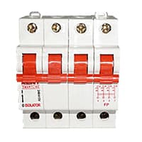
4 pole MCB for 4-Wires Connections, the one additional 4th pole for Neutral Wire Connection so that between Neutral and any of the other three will supply. In 4-Pole MCB the Neutral Pole is also having Protective release as in the Phase Poles connection. 3 Phase Supply with Neutral. TPN means triple pole TP + Neutral which is 3 - phases and Neutral. but the Protection is given for 3 Phases only and in 4 poles MCB Protection is given to all 3-Phases as well as Neutral. In the case of a 4-pole MCB. A Purpose is not to protect the Neutral but it is rather to Isolate the Neutral.
02. DP MCB:
DP MCB In 2 Pole MCB, switching & protection is affected in phases and the neutral. A Double Pole or DP Switch is a Switch that Controls 2 Circuits at the same time. In terms of Residential Switching, this Normally means it Switches the live and Neutral at the same time. In Layperson Terms, Double Pole switches or DP Switches are Exclusively Designed to Control 2 Different Electrical Circuits at the same time, which allows the Appliances to Isolate safely and reliably. Fan or light Combinations and Medical Equipment are some of the many applications for DP Electrical Switches and Electrical components.

03. Magnetic Contactor:

A magnetic contactor is an electromagnetic switching device. It is generally used for controlling 3-phase Motors. The operation of a magnetic contactor is similar to that of a Relay. but a relay is used for low-power or low-voltage connections, and a magnetic contactor is used for high-power or high-voltage connections. As soon as the supply is applied to the magnetic contactor coil. its normally open contacts are closed and normally closed contacts are opened and the associated devices are also operated. This is how a magnetic contactor works.
04. Overload Relay:
Overload Protection is Protection Against a Running Overcurrent That Would Cause Overheating of The Protected Equipment. Hence, An Overload is Also a Type of Overcurrent flow. Overload Protection Typically Operates on an Inverse Time curve where the Tripping Time Becomes less as the Current Increases. This Overload Protector is an Essential Component for Many Sockets Power Systems. The Top-Quality Overload Protector can Effectively Protect Electrical Products from Power Surges.

05. NO Switch:

NO (Normally Open) Terms Refer to a Type of Dry Contact or Wet Contact. A Push to Make Switch Allows Electricity to flow Between its 2 contacts when held in. When the button is released, the Circuit is broken. This type of Switch is also known as A Normally Open (NO) Switching system. As its name implies, a Normally Open (NO) Switch Contact or “a Contact” is a Switch. Put very simply, a Normally Open Sensor will have no Current When in a Normal State But When it Enters an Alarm State it will have +5V applied to the Circuit.
06. NC Switch:
An NC (Normally Closed) Push Button is a Push Button That, In Its Default State, Makes Electrical Contact With The Circuit. An NC (Normally Closed) Push Button is a Push Button that, in its Default State, Makes electrical Contact With the Circuit. When The Button Is Pressed Down, The Switch no Longer Makes Electrical Contact And The Circuit is Now Open. When The Button is Not Pressed, Electricity Can Flow, But When it is Pressed The Circuit is Broken. This type Of Switch is Also known As a Normally Closed (NC) Switch.

07. Emergency Switch:
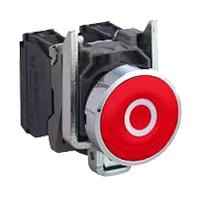
An Emergency Stop button, also known as an E-Stop, is for The person using the machinery and is a fail-safe control switch that provides safety both for the machinery. The Purpose of the emergency Push Button is to Stop the Machinery quickly when there is a risk of injury or the Workflow Requires Stopping. All Machinery Requires an Emergency Stop button to Reduce Risk. Buttons are typically red, Often With a Yellow Background to Ensure a Vivid and Easily Identified Solution.
08. 3 Phase Motor:
A 3-phase electric motor uses a 3-phase Power Supply to Convert Electric Energy into Mechanical Energy. It contains four Wires (Three hot Wires and one Neutral Wire) and Uses 3 Alternating Currents of the Same Frequency. Since it Generates a Rotating Magnetic Field, it does not need a Capacitor for the Startup. Some 3-phase Motors are Reversible, Which Means they can serve as Generators by Turning Mechanical Energy into Electrical Energy.

Thank You for visiting the website. Keep visiting for more Updates.
Frequently asked questions
The Start-Stop function temporarily stops the engine when the car is stationary and restarts it automatically so that driving resumes. In concrete terms, it works as follows, if you stop your vehicle, in this example an automatic car, at a red light, the engine automatically switches off.
As a rule, a motor can be controlled from any number of locations provided that we follow these simple rules, Wire all normally closed stop buttons in series with each other, Wire all normally open start buttons in parallel with each other, or Connect the holding contact in parallel with the start buttons.
A wiring diagram shows the relative layout of the components or the wire connections between them. This type of diagram shows the physical relation of all devices in the system, and the conductor terminations between these devices, and is commonly used in motor control installations.
The Auto-Start-Stop indicator illuminates green when the engine stops. It flashes amber or a message appears when you need to take action. The Auto-Start-Stop indicator illuminates gray with a strikethrough that the system is not available.
Basically, stop or start shutting down the engine whilst the vehicle is stationary. In the manual of the cars, this also happens when the car is in neutral. When the driver is ready to set off it would start again usually after the clutch has been pressed. In automatic motor pumps, the system is a lot easier to use.
Read more Single Phase Wiring
What is a kilowatt-hour (kWh) | kwh formula | What does kwh mean
Introduction to Electrical Units and CircuitskW and kWh on your electricity bill As your home uses electricity during...
What is the Difference Between kVA | What does KVA mean | kVA formula
Difference Between KVA ExplainedWhat does KVA Mean? There are technical terms aplenty when it comes to generators, and...
Power Factor | Power Unit | Energy | Electricity Unit
Power factor definition | Calculating Power FactorPower Factor Values In a purely resistive circuit, the power factor...
0 Comments