5 pin relay wiring diagram:
This diagram shows how to make 5 pin relay wiring diagram. In this circuit we use, two DP MCBs ( Double Pole Minature Circuit Breaker ), a motor protector device, a magnetic contactor, a 5-pin relay, an SP MCB ( Single Pole Minature Circuit Breaker ), a timer block, a 2-pin socket, a 2 plug, a single phase motor, and a floating switch.
Advertisements
Diagram of 5 pin relay wiring:

Components needed For this Project:
You can get the components from any of the sites below:
- DP MCB 20A [See Buy Click Amazon]
- MPCB Switch [See Buy Click Amazon]
- Magnetic Contactor 40A [See Buy Click Amazon]
- 5 Pin Relay DC Line [See Buy Click Amazon]
- SP MCB 10A [See Buy Click Amazon]
- 2 Pin board Socket [See Buy Click Amazon]
- Terminal Block [See Buy Click Amazon]
- Single Phase Motor (1 HP) [See Buy Click Amazon]
- Float Switch Water Level Controller [See Buy Click Amazon]
*Please note: These are affiliate links. I may make a commission if you buy the components through these links. I would appreciate your support in this way!
Advertisements
Components used to make the 5 pin relay wiring diagram:
01. DP MCB:

DP MCB In 2 Pole MCB, switching & protection is affected in phases and the neutral. A Double Pole or DP Switch is a Switch that Controls 2 Circuits at the same time. In terms of Residential Switching, this Normally means it Switches the live and Neutral at the same time. In Layperson Terms, Double Pole switches or DP Switches are Exclusively Designed to Control 2 Different Electrical Circuits at the same time, which allows the Appliances to Isolate safely and reliably. Fan or light Combinations and Medical Equipment are some of the many applications for DP Electrical Switches and Electrical components.
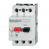
02. MPCB :
MPCB = Motor Protection Circuit Breakers. A protection system against electrical faults, such as short circuits for AC Line 220V. line-to-ground faults, and line-to-line faults. Electrical faults that are below the MPCB is breaking capacity can be interrupted by the board.MCBs are designed for a wide variety of functions circuit protection functions while MPCBs are used for the specific function of protecting circuits driving electric motors.
03. Magnetic Contactor:

A magnetic contactor is an electromagnetic switching device. It is generally used for controlling 3-phase Motors. The operation of a magnetic contactor is similar to that of a Relay. but a relay is used for low-power or low-voltage connections, and a magnetic contactor is used for high-power or high-voltage connections. As soon as the supply is applied to the magnetic contactor coil. its normally open contacts are closed and normally closed contacts are opened and the associated devices are also operated. This is how a magnetic contactor works.
04. 5-Pin Relay:
Relay is a switching device. If current flows through the coil, the coil inside the coil is magnetized and the circuit can be regulated and controlled by on-off switching. Relays are also called protective devices because they close the circuit, component, or device in an emergency to protect it from being burned or damaged. Almost all relays have two source pins and the coil is connected to that source pin. If voltage is applied to this coil then a magnet is created in this coil.

05. SP MCB:

In single-pole MCB, Switching and protection are Affected in only one Phase. Single phase supply to break the phase only. A single Pole breaker is Typically used with 120-volt Circuits, and a 6-20 amps Miniature Circuit Breaker. They are constructed with one Line Wire and one Neutral wire. A Single Pole switch is the most basic General-Purpose switch that you use to Control a light or another device from one location. These Switches have 2 Brass-Colored screw Terminals Connected to the hot Power source wires. Pole refers to the number of Circuits Controlled by the Switch SP Switches Control only one Switch Electrical Circuit.
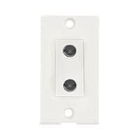
06. Power Socket:
A Power Socket is a Device to Which Electrical Devices Can Be Connected to Receive the Electric Current Required For Their Operation. Connected by a System of Cables to a Power Source, Usually, an Electricity Generation Facility operated by an energy Production company, generally has no moving parts. Instead, it contains metal strips that make contact with the prongs of an Electric plug inserted into the socket. It is Through these Contacts That the Electric current is Transmitted. Electrical Devices that connect to a Power Source Through a Power Socket are Considered to be Portable Because they can easily be Connected and Disconnected From the Power Source.
07. Terminal Block:
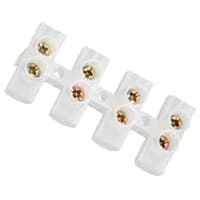
Terminal Clocks are Connectors That Terminate a Single wire and Connect it to a circuit or other system. Terminal Blocks come in a range of shapes, Sizes, and ratings, but Always Terminate a single Wire and are Never multi-pole. Terminal Blocks are used to Secure or Terminate Wires and, in Their Simplest form, Consist of Several Individual Terminals Arranged in a long strip system. Terminals are Useful for Connecting the Wiring to the GND or, in the Case of Electrical power, for Connecting Electrical Switches and Outlets to the Mains side.
08. Single Phase Motor:
A Single-Phase Motor is an Electrically-Powered Rotary Machine That Can Turn Electric Energy into Mechanical Energy. It Works by Using a Single-Phase Power Supply. Single-phase Motors Are Used in Equipment And Machines That Are Smaller in Size And Require Lower Horsepower. This Includes Equipment Such As Refrigerators, Pumps, Compressors, Fans, and Portable Drills. Single-phase motors Have a Similar Construction to The 3-phase Motor, Including an AC Winding That is Placed on The Stator And Short-Circuited Conductors That are Placed in a Cylindrical Rotor.

05. Float Switch:

A Float Switch is a type of Level Sensor Device Used to Detect the level of liquid within a tank. The Switch May be Used to Control a Pump, as an Alarm, as an Indicator, or to Control Other Devices. 1 type of Float Switch Uses a Mercury Switch Inside a Hinged float. Another common type is a Float Switch That Raises a rod to Actuate a Microswitch. One Pattern Uses a reed Switch Mounted in a Tube Float, Containing a Magnet, Surrounding the Tube, and Guided by it.
Thank You for visiting the website. Keep visiting for more Updates.
Frequently asked questions
The size is 1.41 x 0.94 x 0.63 inch/ 3.6 x 2.4 x 1.6 cm approximately. Our 30A 12V relay can be used to control the circuit diagram of components with high amperage loads on vehicles, such as headlights, fuel pumps, or cooling fans.
Generally, a power supply relay gets power from the battery source, and the electromagnet draws the armature. Also, includes a moveable arm made of iron. It uses the spring to hold the armature in place. The armature gets pulled to the coil directly to reach contact and close the circuit.
What will be more likely be different is just about everything else: the voltage of the coil, at which it is designed to operate. Rating of the contacts, how many volts, or how many amperes. Pin-out, which pin has what internal connection?
Coil voltage — machine-tool relays usually 24 VDC, 120, and 250 VAC, relays for switchgear may have 125 V or 250 VDC coils, Coil current flow is the Minimum current required for reliable operation and minimum holding current, as well as effects of power supply dissipation on coil temperature at various duty cycles.
Yes. With the above figure, you can surely run a 5v relay on 12v. You just have to connect a cheap and reliable regulator I.C. LM 7805 in the above shown way.
Read more Single Phase Wiring
What is a kilowatt-hour (kWh) | kwh formula | What does kwh mean
Introduction to Electrical Units and CircuitskW and kWh on your electricity bill As your home uses electricity during...
What is the Difference Between kVA | What does KVA mean | kVA formula
Difference Between KVA ExplainedWhat does KVA Mean? There are technical terms aplenty when it comes to generators, and...
Power Factor | Power Unit | Energy | Electricity Unit
Power factor definition | Calculating Power FactorPower Factor Values In a purely resistive circuit, the power factor...
0 Comments