Timer With Sensor Wiring:
This diagram shows how to make Timer With Sensor Wiring. In this circuit, we use an RCBO ( Residual Current Breaker with Over-Current ), a DP MCB ( Double Pole Minature Circuit Breaker ), a timer, two motion sensors, and two 2-way switches. First, we need to connect the RCBO with the power source, then connect the DP MCB with the RCBO, then connect the timer with DP MCB, then connect the sensors and switches with the timer.
Advertisements
Diagram of Timer With Sensor Wiring:

Components needed For this Project:
You can get the components from any of the sites below:
- DP RCBO 20A [See Buy Click Amazon]
- DP MCB 20A [See Buy Click Amazon]
- 8 Pin Timer 220V AC [See Buy Click Amazon]
- Motion Sensor [See Buy Click Amazon]
- Gang Switch [See Buy Click Amazon]
*Please note: These are affiliate links. I may make a commission if you buy the components through these links. I would appreciate your support in this way!
Advertisements
Components used to make the Timer With Sensor Wiring:
01. RCBO:
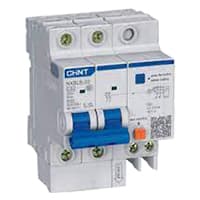
An RCBO protects Electrical equipment against 2 types of faults. Residual current and over current. Residual current. or earth leakage as it is sometimes referred to, occurs when there is a break in the circuit which can be caused by faulty electrical wiring or if the wire is accidentally cut. When there is a break in the circuit which may be due to faulty electrical wiring or accidental cutting of the wire. To prevent the current from being redirected and causing an electric shock. the RCBO current breaker stops it.
02. DP MCB:
DP MCB In 2 Pole MCB, switching & protection is affected in phases and the neutral. A Double Pole or DP Switch is a Switch that Controls 2 Circuits at the same time. In terms of Residential Switching, this Normally means it Switches the live and Neutral at the same time. In Layperson Terms, Double Pole switches or DP Switches are Exclusively Designed to Control 2 Different Electrical Circuits at the same time, which allows the Appliances to Isolate safely and reliably. Fan or light Combinations and Medical Equipment are some of the many applications for DP Electrical Switches and Electrical components.

03. Timer:

A timer is a type of time-switching device that controls and controls Electrical circuits and electrical and electronic devices through time setting (on/off). The timer is basically 8-pin. Like other controlling devices the timer has a coil and when this coil is magnetized, the timer works on/off. The timer has 2 common ends and each common end has normally close and normally open options. When the timer is set by time, the timer trips at the end of that time and turns the common is normally closed (on) to open (off) and normally open (off) to close (on). This is how the timer works.
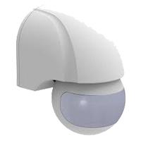
04. Motion Sensor:
Photocells and Motion Sensors are Electronic Devices you can use to Manage Indoor or Outdoor Lighting. The Main Difference Between Photocells and Motion Sensors is that the Former Detects change in light Levels, and The Latter React to Physical Movement. Movement in the Detection area Changes the Reflected Signals and Activates the Sensor. They also save Energy by Turning Themselves off when Light is Unnecessary. Many Motion Sensors use a Combination of Detection Methods to Provide enhanced Coverage and eliminate false positives. The adjustable timers built into some Sensors let you Control how long the Attached Lights Remain Active after it Detects Motion.
05. SPST Switch:

An SPST (Single Pole Single Throw) Switch is a Switch That only Has a Single Input and can Connect Only to one Output. This means it Only Has one Input Terminal and Only 1 Output Terminal. A Switch is a Mechanical or Controlling Device That Changes the Flow of Current Direction or Interrupts the Flow of Current Within a Circuit diagram. An electrical line using Single Pole Single Throws (SPST) is Perfect for on-off switching. When the SPST is closed, the Circuit is Closed and the light from the lamp switches on the system. When The Single Pole Single Throw (SPST) is then opened, the light from the lamp goes out and the Circuit is off.
Thank You for visiting the website. Keep visiting for more Updates.
Read more Single Phase Wiring
What is a kilowatt-hour (kWh) | kwh formula | What does kwh mean
Introduction to Electrical Units and CircuitskW and kWh on your electricity bill As your home uses electricity during...
What is the Difference Between kVA | What does KVA mean | kVA formula
Difference Between KVA ExplainedWhat does KVA Mean? There are technical terms aplenty when it comes to generators, and...
Power Factor | Power Unit | Energy | Electricity Unit
Power factor definition | Calculating Power FactorPower Factor Values In a purely resistive circuit, the power factor...
0 Comments