Emergency stop button wiring:
This diagram shows how to make Emergency stop button wiring. In this circuit, we use a DP MCB ( Double Pole Miniature Circuit Breaker ), an RCCB ( Residual Current Circuit Breaker ), a magnetic contactor, a resistance coil, a timer, and an emergency stop switch. First, we need to connect the DP MCB with a power source, then connect the RCCB with the DP MCB, then connect the contactor, then connect the timer, then connect the emergency stop switch.
Advertisements
Diagram of Emergency stop button wiring:

Components needed For this Project:
You can get the components from any of the sites below:
- DP MCB 32A [See Buy Click Amazon]
- DP RCCB 16A [See Buy Click Amazon]
- Magnetic Contactor 25A [See Buy Click Amazon]
- 8 Pin Timer 220V AC [See Buy Click Amazon]
- Emergence Switch [See Buy Click Amazon]
*Please note: These are affiliate links. I may make a commission if you buy the components through these links. I would appreciate your support in this way!
Advertisements
Components used to make the Emergency stop button wiring:
01. DP MCB:

DP MCB In 2 Pole MCB, switching & protection is affected in phases and the neutral. A Double Pole or DP Switch is a Switch that Controls 2 Circuits at the same time. In terms of Residential Switching, this Normally means it Switches the live and Neutral at the same time. In Layperson Terms, Double Pole switches or DP Switches are Exclusively Designed to Control 2 Different Electrical Circuits at the same time, which allows the Appliances to Isolate safely and reliably. Fan or light Combinations and Medical Equipment are some of the many applications for DP Electrical Switches and Electrical components.
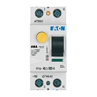
02. RCCB:
The Residual Current Circuit breaker RCCB is the Safest device to detect and Trip against Electrical Leakage current. This ensures protection against Electric shock Caused by indirect contact. Circuit breakers (CB) are automatically Operated Electrical Switches that Protect Electrical Circuits from Short-Circuiting or Overloading systems. It Protects against many major accidents. RCCB Circuit Breaker is an Electrical Wiring device whose function is to disconnect the current in the circuit.
03. Magnetic Contactor:

A magnetic contactor is an electromagnetic switching device. It is generally used for controlling 3-phase Motors. The operation of a magnetic contactor is similar to that of a Relay. but a relay is used for low-power or low-voltage connections, and a magnetic contactor is used for high-power or high-voltage connections. As soon as the supply is applied to the magnetic contactor coil. its normally open contacts are closed and normally closed contacts are opened and the associated devices are also operated. This is how a magnetic contactor works.
04. Timer:
A timer is a type of time-switching device that controls and controls Electrical circuits and electrical and electronic devices through time setting (on/off). The timer is basically 8-pin. Like other controlling devices the timer has a coil and when this coil is magnetized, the timer works on/off. The timer has 2 common ends and each common end has normally close and normally open options. When the timer is set by time, the timer trips at the end of that time and turns the common is normally closed (on) to open (off) and normally open (off) to close (on). This is how the timer works.

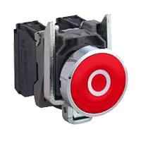
An Emergency Stop button, also known as an E-Stop, is for The person using the machinery and is a fail-safe control switch that provides safety both for the machinery. The Purpose of the emergency Push Button is to Stop the Machinery quickly when there is a risk of injury or the Workflow Requires Stopping. All Machinery Requires an Emergency Stop button to Reduce Risk. Buttons are typically red, Often With a Yellow Background to Ensure a Vivid and Easily Identified Solution.
Thank You for visiting the website. Keep visiting for more Updates.
Frequently asked questions
They should ALWAYS be in series. If they're in parallel, either you shall have to press all four of them to drop out the safety inputs, or you're wiring them normally open, which was just as bad. Generally, I personally would consider it fine to wire any number of the e/stops into the same inputs.
As a special function button commonly used in industry, the emergency stop button is usually installed in the control panel or button box. Its structure mainly includes 3 parts: actuator, holder, or switching elements. The actuator is used to operate and release components, usually with a push rod and spring to achieve action.
closed In most cases, emergency stop buttons were normally closed (NC). This means that when the button is not pressed, the circuit is closed, and power continues to flow, allowing the machine or equipment to operate normally.
E-stops shall be located at each operator's control station. In addition, other locations can be considered according to a risk analysis, including entrance and exit locations. See ISO( 13850-4), Safety Requirements; 3, Terms and Definitions; and 2, Normative References.
Now the emergency stop button on the other hand sits in the exact opposite state of the general pushbutton. It was always normally closed, meaning that the circuit was already connected so that power could flow freely from the source to the piece of equipment, or load, that needed it.
Read more Single Phase Wiring
What is a kilowatt-hour (kWh) | kwh formula | What does kwh mean
Introduction to Electrical Units and CircuitskW and kWh on your electricity bill As your home uses electricity during...
What is the Difference Between kVA | What does KVA mean | kVA formula
Difference Between KVA ExplainedWhat does KVA Mean? There are technical terms aplenty when it comes to generators, and...
Power Factor | Power Unit | Energy | Electricity Unit
Power factor definition | Calculating Power FactorPower Factor Values In a purely resistive circuit, the power factor...
0 Comments