Ampere meter in Voltmeter Wiring:
This diagram shows how to make an Ampere meter in Voltmeter Wiring. In this circuit, we use a single-phase water pump motor, a DP MCB ( Double Pole Miniature Circuit Breaker ), a voltmeter, an ampere meter, a pump controller, and a digital panel meter. First, we need to input power into DP MCB, then input power into the voltmeter and ampere meter, then connect the motor controller and motor with this power source. Now this circuit is ready for use. This circuit is very simple and very easy to make the connection. If you want to know more about this circuit please check our video below the post.
Advertisements
Diagram of Ampere meter in Voltmeter Wiring:

Components needed For this Project:
You can get the components from any of the sites below:
- DP MCB 16A [See Buy Click Amazon]
- single phase Volt Meter [See Buy Click Amazon]
- Single Phase Amperemeter [See Buy Click Amazon]
- Pump Controller [See Buy Click Amazon]
- DC Digital Volt Ampere Meter [See Buy Click Amazon]
- Single Phase Motor (1 HP) [See Buy Click Amazon]
*Please note: These are affiliate links. I may make a commission if you buy the components through these links. I would appreciate your support in this way!
Advertisements
Components used to make the Ampere meter in Voltmeter Wiring:
01. DP MCB:

DP MCB In 2 Pole MCB, switching & protection is affected in phases and the neutral. A Double Pole or DP Switch is a Switch that Controls 2 Circuits at the same time. In terms of Residential Switching, this Normally means it Switches the live and Neutral at the same time. In Layperson Terms, Double Pole switches or DP Switches are Exclusively Designed to Control 2 Different Electrical Circuits at the same time, which allows the Appliances to Isolate safely and reliably. Fan or light Combinations and Medical Equipment are some of the many applications for DP Electrical Switches and Electrical components.
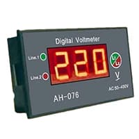
02. Voltmeter:
An instrument that measures the potential difference between any two points in a circuit directly in volts is called a voltmeter. A voltmeter is an Electrical instrument that directly measures the potential difference between any 2 points in a circuit in volts. The voltmeter is connected in parallel with the 2 points in the circuit where the potential difference is to be measured. This instrument consists of a galvanometer. Like an electric cell or an ammeter, a voltmeter has 2 terminals, a positive and a negative terminal. Usually, the positive end is red and the negative end is black.

03. Amperemeter:

Ammeter, an instrument, with the help of which the flow of electricity can be measured directly in Electrical units, amperes. It is a galvanometer with very low resistance. As a result, the entire current flows through the meter coil. Current is measured with an ammeter. So it can be said that the device that measures the flow of current in an ampere unit is an ammeter. Electric current is the flow of electrons whose unit is an ammeter. So it can be said that the device that measures the flow of current in an ampere unit is an ammeter. An ideal ammeter has no internal resistance. But in reality. the ammeter has little internal resistance. The range of the ammeter depends on this resistance.
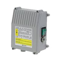
04. Pump Controller:
single-phase source well with a submersible pump controlled by a pressure switch. The pressure switch senses pressure in the power supply line. When line pressure drops, the pressure switch signals the pump control box to start the well water pump. Pump control can include simply turning a pump on and off, or more advanced controls for pump speed, output pressure, etc.
05. Digital Panel Meter:
The volt meter is used to measure voltage. With the load, it is connected in parallel. The common voltmeter and ammeter have a similar design and operate on the same logic. A reading is acquired when current passes through the voltmeter coil at a rate proportional to the voltage. This meter has a very high internal resistance. A volt meter is coil is constructed of several strands of thin wire.
06. Pump Motor:
A Single-Phase Motor is an Electrically-Powered Rotary Machine That Can Turn Electric Energy into Mechanical Energy. It Works by Using a Single-Phase Power Supply. Single-phase Motors Are Used in Equipment And Machines That Are Smaller in Size And Require Lower Horsepower. This Includes Equipment Such As Refrigerators, Pumps, Compressors, Fans, and Portable Drills. Single-phase motors Have a Similar Construction to The 3-phase Motor, Including an AC Winding That is Placed on The Stator And Short-Circuited Conductors That are Placed in a Cylindrical Rotor.

Thank You for visiting the website. Keep visiting for more Updates.
Frequently asked questions
The voltmeter has very high resistance whereas an ammeter has very low resistance. Thus in order to use an ammeter in the place of a voltmeter, we must add a very high resistance in series with the ammeter so that it works as a voltmeter.
An Ammeter is used to measure the current flowing through a component/circuit diagram. Since the current flow remains the same in the series connection and also the resistance of an ammeter is very small it does not affect the current flow to be measured. So, an ammeter is connected in series to measure current flow.
Ampere is the unit that we use to quantify the current flowing in the system. An ampere is equivalent to a charge of 1 Coulomb per second.
Magnetic field strength as measured by ampere per meter. The formula used to measure a coiled conductor is H = IN/L, where I is the amount of current flow, N is the number of coils and L is the length of the coil in meters.
Since in series connection, the current flow remains constant. We know from Ohm law that $V=IR$, or $I=\dfrac{V}{R}$, clearly the more the resistance of the ammeter, the less the current which flows through the ammeter. Hence in order to measure the maximum current in the circuit diagram , the ammeter must have low or negligible resistance.
Read more Single Phase Wiring
What is a kilowatt-hour (kWh) | kwh formula | What does kwh mean
Introduction to Electrical Units and CircuitskW and kWh on your electricity bill As your home uses electricity during...
What is the Difference Between kVA | What does KVA mean | kVA formula
Difference Between KVA ExplainedWhat does KVA Mean? There are technical terms aplenty when it comes to generators, and...
Power Factor | Power Unit | Energy | Electricity Unit
Power factor definition | Calculating Power FactorPower Factor Values In a purely resistive circuit, the power factor...
0 Comments
Trackbacks/Pingbacks