2 Way light switch wiring
Wiring diagram for controlling a light from three or more locations using two way and intermediate switches for flexible ON/OFF control.

electrical wiring intermediate switch
The 2-way switches and the intermediate switch wiring allow three or more locations to be able to turn on/off a single light fixture with the ease of toggling between the positions.
Formula & Table Summary:
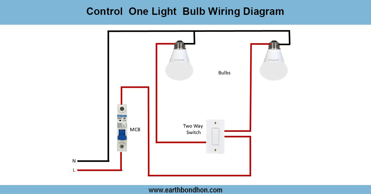
Components: Two SPDT two way switches (ends), one or more intermediate DPDT switches (middle), light fixture, live (L), neutral (N), traveler wires.
Connections: Live supply → Common terminal of first two way switch; traveler wires link two way and intermediate switches; common terminal of last two way switch → light fixture; neutral connects directly to light.
Operation: Any switch toggle changes current path, turning light ON or OFF.
Safety: Power off before wiring; use correct wires and follow electrical codes.
| Component | Connection | Function |
|---|---|---|
| Two Way Switch 1 Common | Live Supply | Power input |
| Two Way Switch 1 Travelers | Connect to Intermediate Switch | Switching paths |
| Intermediate Switch Terminals | Connects traveler wires in crossover manner | Changes traveler connections |
| Two Way Switch 2 Travelers | Connect to Intermediate Switch | Switching paths |
| Two Way Switch 2 Common | Light Fixture | Load control |
| Neutral | Connects to Light Fixture | Completes circuit |
multi-location light switch wiring
Use of the two way switch intermediate connection diagram illustrates the wiring of lighting circuit controlled at three or more loads with two way switches at each end and one or more two way switches between the loads. The middle switch is a crossover that permits the isolation of traveler wire so that traveling can be controlled remotely. The wiring arrangement is good where there is a long corridor, stairs or large room with different entrances whereby ON/OFF control is available at any switch. The live feed is fed into the shared terminal on the first two way switch, the traveling wires run across joining switches such as the intermediate switch, and the common on the last two way switch runs to the light fitting. Light is linked with neutral wires.
two way switch installation
| Two Way Switch 1 | Intermediate Switch | Two Way Switch 2 | Light Status |
|---|---|---|---|
| Up | Straight | Up | OFF |
| Up | Crossover | Down | ON |
| Down | Crossover | Up | ON |
| Down | Straight | Down | OFF |