How to Make Modified Sinus Wave Inverter 1000W
Learn how to make a 1000W modified sine wave inverter at home. Step-by-step DIY guide with components, circuit, safety tips, and AC output.

What is a Modified Sine Wave Inverter?
A modified sine wave inverter converts DC voltage from batteries into AC voltage with a waveform that approximates a sine wave.
Advantages:
- Cost-effective and easy to build
- Powers most household appliances
- Suitable for LED lights, fans, and chargers
Limitations:
- May cause humming in audio equipment
- Less efficient for sensitive electronics
Modified sine wave inverter at home
A modified sine wave inverter is a viable solution to convert the DC power stored in a battery into usable AC power. An inverter with a 1000W can supply small appliances and lights in the home, as well as electronic devices. Modified sine wave inverter is easier to construct, unlike a pure sine wave inverter, and cost-effective, and can be installed in most home applications.
Here you will know how to make a 1000W modified sine wave inverter in your home by using transistors, a PWM controller, a transformer, and other auxiliary parts. The project will encompass circuit design, components, parts, step-by-step assembly, testing, precautionary measures, and troubleshooting. The project is suitable for all electronics lovers, DIY lovers, and students who desire to have a high-power inverter in their home or portable.
Applications of a 1000W Inverter
- Power backup for home appliances
- Emergency lighting and fans
- Charging electronic devices
- Portable AC power for outdoor activities
- Small workshop tools
- Solar or battery-powered setups
Components Required
| Component | Specification |
|---|---|
| MOSFET/Transistors | IRFZ44N or equivalent, 4–8 pcs |
| PWM Generator IC | SG3525 or NE555 based PWM module |
| Transformer | 12V DC to 220V AC, 1000W |
| Capacitors | 100nF–470µF for filtering |
| Diodes | 1N5408 for rectification and protection |
| Heat Sink | For MOSFET cooling |
| Wires | 12–14 AWG for power connections |
| Fuse | 15A–20A for safety |
| PCB/Breadboard | For assembly |
| Battery | 12V DC, 100Ah or equivalent for 1000W load |
| Switch | For turning inverter ON/OFF |
Working Principle of Modified Sine Wave Inverter
PWM Generation
PWM (Pulse Width Modulation) generates a modified sine waveform and determines AC output voltage and frequency.
Switching Circuit
MOSFETs or transistors act as high-speed switches, switching DC through the transformer primary winding.
Transformer Step-Up
Steps up 12V DC to 220V AC, providing AC output suitable for home appliances.
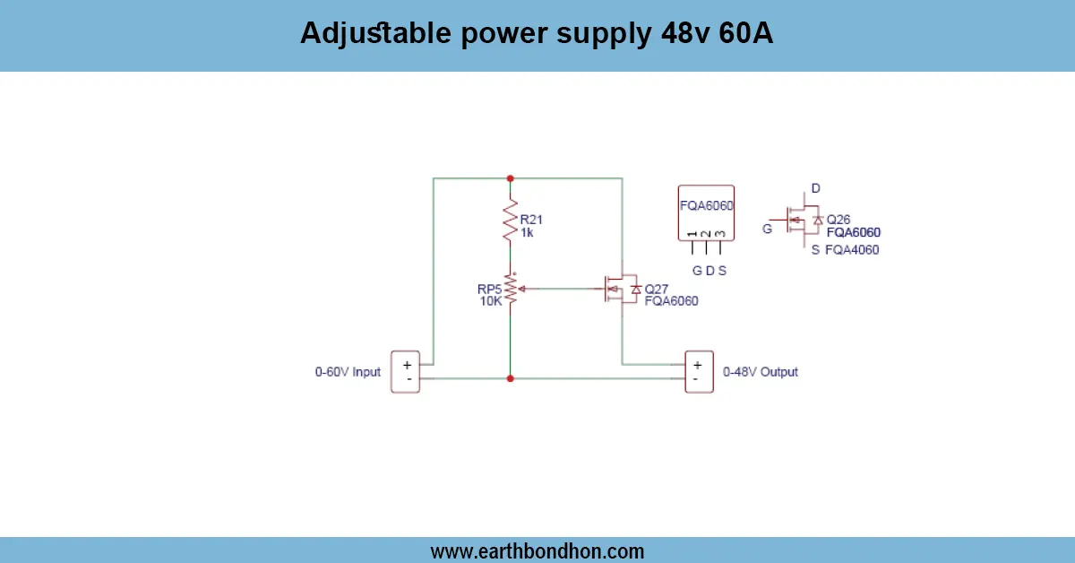
1000W Modified Sine Wave Inverter Circuit Diagram
- Connect PWM IC output to MOSFET gates
- MOSFETs switch 12V DC through transformer primary
- Use diodes and capacitors for waveform smoothing
- Connect fuse and switch for safety
- Transformer secondary delivers 220V AC output
Step-by-Step Construction Guide
- Assemble PWM generator circuit on PCB
- Connect MOSFETs with heatsinks to PCB
- Wire 12V battery to inverter input
- Connect MOSFETs to transformer primary winding
- Add capacitors and diodes for filtering
- Install switch and fuse
- Mount transformer securely
- Double-check all connections and polarities
- Test with multimeter and low-power load
- Connect appliances gradually for full 1000W load
Testing and Usage Instructions
- Test without load initially
- Measure AC output voltage using multimeter
- Gradually connect appliances
- Monitor MOSFET heating and transformer temperature
Safety Precautions
- High voltage AC can be dangerous
- Always use proper insulated wires and fuse
- Keep MOSFETs on heatsink to avoid overheating
- Avoid touching live wires
- Do not exceed battery or transformer ratings
Tips for Efficient Operation
- Use proper heat sinks for cooling
- Ensure battery is fully charged for 1000W operation
- Use short thick wires for power connections
- Maintain safe distance from sensitive electronics
Troubleshooting Common Issues
No AC Output
Check PWM module and MOSFET connections. Verify battery voltage.
Low AC Voltage
Check transformer connections and load. Adjust PWM duty cycle.
Overheating MOSFETs
Improve cooling with a bigger heatsink. Check PWM frequency and load balance.
Frequently Asked Questions - How to Make Modified Sinus Wave Inverter 1000W:
What is a modified sine wave inverter?
An inverter that converts DC to AC with an approximated sine waveform.
Can I make a 1000W inverter at home?
Yes, using MOSFETs, PWM IC, transformer, and battery.
Which MOSFETs are recommended?
IRFZ44N or equivalent high-power MOSFETs.
What battery is needed for 1000W load?
12V battery, preferably 100Ah or higher.
Do I need heatsinks?
Yes, to prevent MOSFETs from overheating.
Can it power all home appliances?
It can power small to medium appliances, not heavy inductive loads.
Is it safe?
Yes, with proper insulation, fuse, and cautious handling of AC output.
How to test before full load?
Use multimeter and small load first to verify voltage and waveform.
Can I use PWM module for waveform control?
Yes, PWM controls the modified sine waveform and voltage.
What if AC voltage is low?
Check transformer wiring, PWM duty cycle, and battery voltage.