Proximity Sensor Circuit Adjustable Range
Learn how to build a proximity sensor circuit with an adjustable range using simple components. Step-by-step guide includes circuit diagram, working principle, assembly, and applications for DIY electronics projects.

Introduction to Proximity Sensor Circuits
The sensors are close sensors that sense objects without touching them, and thus, they are great for automation and safety. They may be based on infrared light, ultrasonic waves, or capacitive sensing; however, the infrared-based design It is most popularly used in DIY projects due to its simplicity and cost. The adjustable range will enable you to fine-tune The detection range gives it more flexibility in performing various tasks.
inductive proximity sensor circuit diagram
A proximity sensor circuit, which has an adjustable range, is a universal electronic project through which you can Detect the presence of an object without touching it physically. Such a sensor finds extensive applications in security systems, automated lighting, robotics, and home automation. With the help of (about) an infrared LED, a photodiode or LDR, an IC555 timer or LM393 comparator, and a potentiometer, it is possible to create a basic and effective circuit. The adjustable range ability enables you to adjust the range that the sensor can detect objects, and therefore, it is applicable in various uses. Some of the components required, the working principle, the circuit diagram, and Instructions on assembly, tips on testing, and troubleshooting the circuit will be discussed in this guide, and you shall be able to put your own proximity sensor circuit together with an adjustable range to implement your own DIY electronics projects.
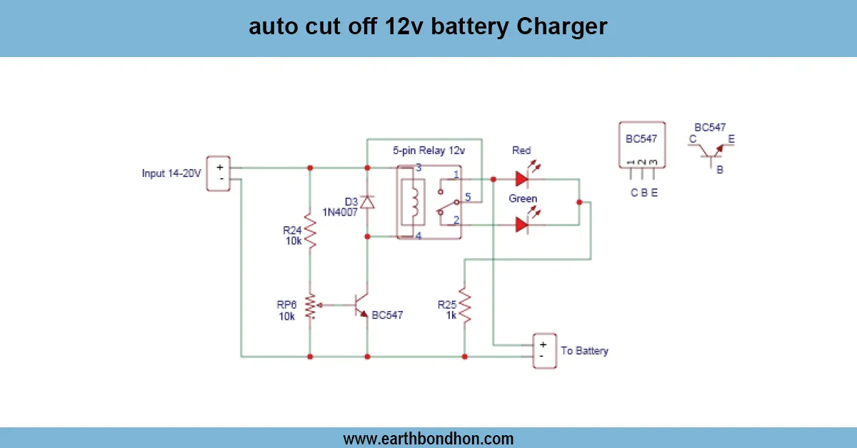
Can BC547 Replace an NTC?
Understanding NTC Thermistors
NTC thermistors detect temperature changes and provide a variable resistance.
- Often used in overcurrent protection, battery monitoring, and temperature alarms.
- Resistance decreases as temperature rises.
BC547 as a Voltage/Current Switch
BC547 cannot sense temperature like an NTC. It can act as a switch when the voltage at its base crosses ~0.7V..
By using a voltage divider, we can simulate the threshold behavior of an NTC and trigger a load.
Components Required for Replacement Circuit
BC547 Transistor
Acts as the switching element. Can drive low-current loads or drive a relay for higher currents.
Resistors and Capacitors
Resistors form the voltage divider to set the threshold voltage. Capacitors stabilize the circuit and prevent false triggering.
Buzzer or LED Load
Used to indicate when voltage/current crosses threshold.
Power Supply
Provides voltage to the circuit and the load.
Working Principle
Voltage Divider and Threshold Detection
The voltage divider creates a reference voltage similar to the NTC voltage drop. When input voltage crosses the threshold, the BC547 base voltage reaches 0.7V, turning it ON.
Switching Action of BC547
BC547 saturates when the base voltage exceeds the threshold, and collector current flows, activating the load.
Simulating NTC Behavior
Adjust the resistor values to emulate NTC switching. BC547 only works as ON/OFF, not gradual resistance change.
Sample Circuit Diagram
Voltage Divider with BC547
Vcc --- R1 ---+--- Base of BC547
              |
             R2
              |
             GND
Adjust R1 and R2 to set trigger voltage.
Load Activation
Collector → Load (LED/Buzzer) → Vcc
Emitter → GND
When BC547 conducts, load turns
ON.
Testing and Adjustment
- Power the circuit.
- Vary input voltage to simulate NTC condition.
- Adjust R1/R2 until load activates at desired threshold.
Applications
- Battery low-voltage alarms (replacing NTC trigger).
- Simple overcurrent or power monitoring circuits.
- LED or buzzer activation for threshold detection.
- DIY electronics where NTC acts like a switch.
Safety Precautions
- Ensure BC547 current rating is not exceeded.
- Use a base resistor to limit current.
- Use a relay for high-current loads.
- Verify connections before powering the circuit.
Frequently Asked Questions - Proximity Sensor Circuit Adjustable Range:
What is a proximity sensor circuit?
A circuit that detects the presence of an object without physical contact.
How do I adjust the detection range?
By turning the potentiometer connected to the comparator or IC555 threshold input.
Can it detect all objects?
It works best with objects that reflect infrared light effectively.
What components are needed?
IR LED, photodiode or LDR, IC555 or LM393, potentiometer, resistors, capacitors, and a load (LED/buzzer).
Can I use this for robotics?
Yes, it can detect obstacles or objects in robotic applications.
What power supply is required?
Typically 5V to 12V DC depending on IR LED and ICs used.
Is it suitable for beginners?
Yes, it is simple to assemble on a breadboard or small PCB.
Can I use a buzzer instead of LED?
Yes, the output can drive either a buzzer or LED for indication.
Does ambient light affect performance?
Strong ambient light may affect detection; use IR filter or shield photodiode.
Can this circuit count objects?
Yes, with minor modifications, it can be used for object counting in automation projects.