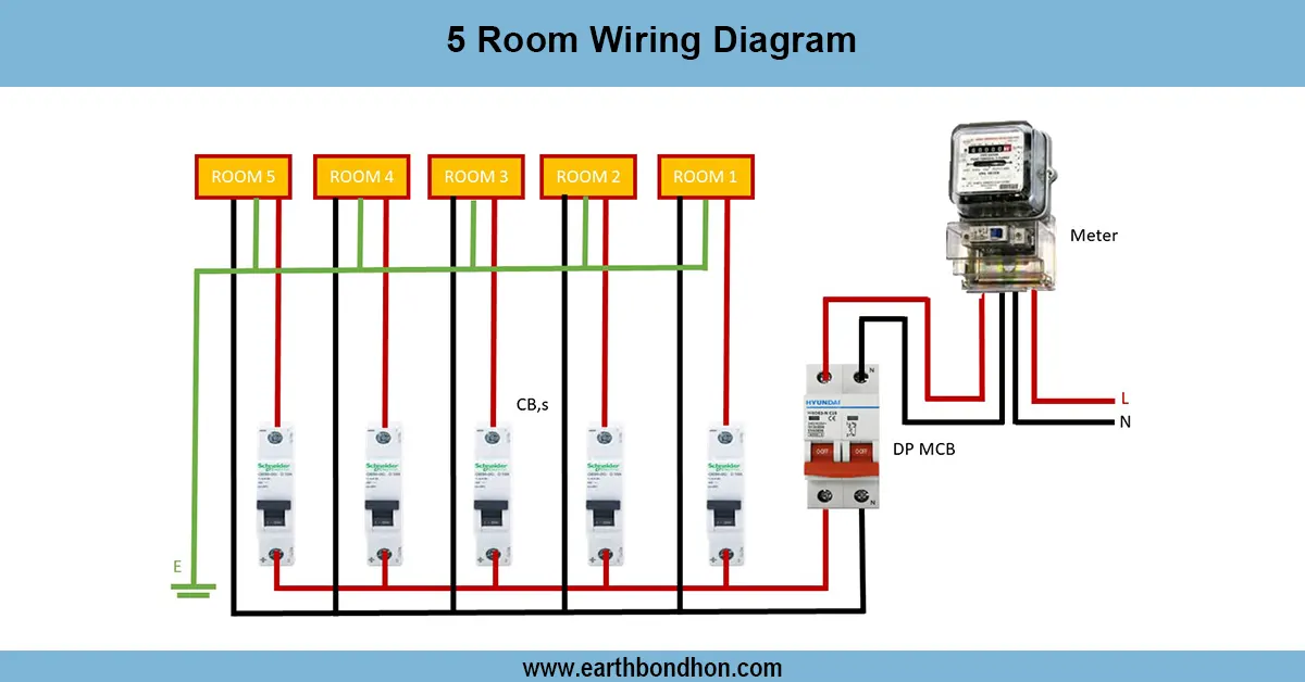
single phase submersible pump wiring Diagram
Learn ampere meter in voltmeter submersible wiring diagram with step-by-step guide for safe motor connection and monitoring.

submersible motor wiring with ammeter
A voltmeter, submersible wiring diagram, and ammeter demonstrate the way to connect measuring devices with a submersible pump to operate safely and monitor. The ammeter is used to measure the current being taken by the motor, and the voltmeter measures the supply voltage. This arrangement comes in handy when it is important to detect overload, low voltage, or unusual conditions in submersible pump motors. Wiring the ammeter in series with the motor and the voltmeter across the supply line enables users to check that everything is working well and to avoid damaging their motor. The common application of it is in agricultural, residential, and industrial water pump systems.
voltmeter ammeter connection for pump
A voltmeter, submersible wiring diagram, and ammeter offer a good way of monitoring and protecting submersible pump motors. In this type of wiring, the ammeter will be attached in series with the circuit of the motor, and the voltmeter will be attached in parallel with the supply line to monitor current being drawn and voltage, respectively. This combination is used to identify abnormal conditions like overload, undervoltage, overvoltage, or blockage of the pump.
It begins with the wiring of the main supply that flows through a protection, either MCB or RCCB, or an overload relay, then to the submersible control panel. The ammeter is connected such that the load current passing through the electric motor passes through the ammeter with the voltmeter across the input terminals. The control panel has the final output, which links to the submersible motor.
The arrangement is typical of agricultural irrigation pump stations, domestic borewell motors, and industrial submersible systems. Constant voltage and current monitoring can help users avoid motor damage, minimize downtime, and ensure longer equipment life. Safe installation and proper earthing are required to operate safely.
Work / Installation (Inputs → Outputs)
A submersible system In a submersible system of motor wiring, the supply line on the distribution board is first connected to a control panel. The ammeter is connected in series with the pump motor in a way that will cause all the current to pass through the ammeter and provide a direct indication of load current. The voltmeter is connected in parallel with the input supply to read the supply voltage. The control panel output is connected to the submersible motor by protective measures by way as MCB, RCCB, or overload relays. Should the motor consume more current, the ammeter scale will indicate an increase in current, and the user will note that there is a potential for overloading or a mechanical jam. In the same manner,under-r oovervoltageses are displayed by the voltmeter. Such wiring also provides protection as well as real-time monitoring, therefore, rendering the system reliable and efficient to operate in the long run.
Testing & Final Adjustments
Once the ammeter and voltmeter are wired in a submersible panel, the system should be tested then it can be run continuously. One, verify that all connections are tight and insulated. Connect the main supply and note the voltmeter reading to adjust to the proper input voltage. Then operate the submersible motor and record the ammeter value to ensure that the current is within the rated levels. Compare the known current with the nameplate of the motor to prevent overloading. When the ammeter indicates high current, it can be due to a blockage in the pump, a low water level, or a mechanical defect. In case the voltmeter reading is low, check supply problems. Ensure that the fault protective MCB or relay operates properly. Mark meters and switches. The last modifications are used to provide safe operation and prevent the untimely failure of the pump.