


Variable Power Supply using LM317
A variable power supply provides adjustable voltage output for electronics testing and DIY projects, allowing safe and precise control from 1.25V up to the input voltage limit.

Variable power supply:
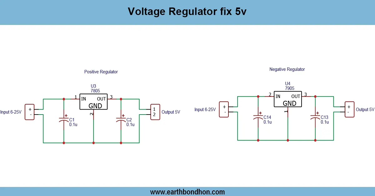
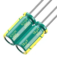
A variable power supply is a mandatory device for electronics enthusiasts, learn, and hobbyists, which can provide them with adjustable DC power to test circuits, energize projects, and conduct experiments. It enables the user to choose the required voltage in a safe current that is usually between 1.25 V and the maximum input voltage. A voltage regulator IC, such as LM317 or a transistor-based circuit, is used to stabilize the voltage and current over the supply. Other elements include potentiometers, resistors, a nd capacitors that make finer adjustments that guarantee stability and low ripple. A versatile, cost-effective, compact variable power supply is suitable for bench work and DIY electronic projects, and learning how to design a practical circuit.
Adjustable lab power source:
A variable power supply is a highly practical device for electronic amateurs, students, and hobbyists, where they can adjust the DC voltage to power circuits, test components, and do experiments. It gives the end user a choice of the output voltage they want in a safe range, usually 1.25 V to the input voltage ratio, depending on the design and regulator employed. Typical applications involve the use of linear voltage regulators, such as the LM317, in transistor-based applications to provide a stable and reliable voltage. The potentiometer, in combination with resistors, enables fine tuning, and input and output capacitors are used to stabilize the voltage, as well as to eliminate the ripple. To avoid thermal problems, heatsinks can be used in the current applications. This kind of power supply is small, inexpensive, and flexible, thus suitable for DIY projects, bench testing, and classroom laboratories. A variable power supply offers a reusable, adaptable, and safe DC supply that is easy to assemble, adjust, and test, and provides practical experience in voltage regulation and circuit management.
⚡ Work & Installation (Input → Output):
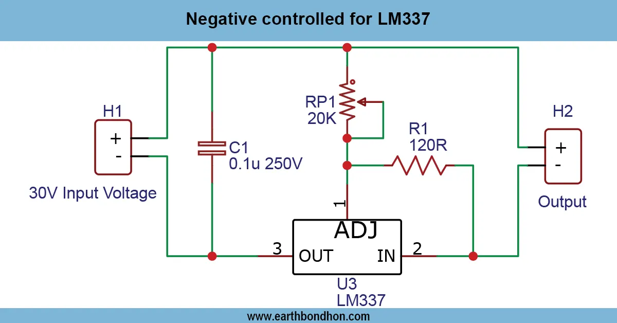
variable power supply-700 text-base leading-relaxed mb-3">A variable power supply operates by controlling the input voltage and giving out a controlled output that could be adjusted with the help of a potentiometer or a network of resistors. Depending on efficiency and current needs, the circuit may be fitted with linear voltage regulators (such as LM317), transistor-based regulators, or switching regulators. Installation: A DC source may be connected to the regulator circuit via installation, capacitors may be added to the regulator circuit to minimize ripple, and the load may be connected to the regulator output terminals. With increased current it t may be necessary to avoid thermal shutdown. Certain designs have current-limiting features as well. Reliability and safety are guaranteed by proper insulation, checking of polarity, and secure connections. The output voltage can then be varied by users to power various electronics, to test LEDs, microcontrollers, and small motorsvariable power supplypply is a vital tool in an electronics lab as well as a DIY project due to its flexibility and precision.Testing & Final Adjustments:
Having an assembled variable power supply, begin by connecting a regulated input voltage into a circuit within the circuit's rating limits. Measure the voltage at the output using a multimeter at different values of the potentiometer or resistor network settings to ensure the control of voltages is smooth and precise. Check the supply with a small dummy load and then connect sensitive electronics. When working with a linear regulator such as LM317, when using it at higher currents, add a heatsink in order to avoid overheating. Installation of input and output capacitors should be done properly in order to ensure stability and minimize voltage ripple. Check current-limiting features, preferably, as a security measure. Select the values of resistors or potentiometers depending on the required voltage output. The supply is tested; after that, it can be safely used to drive LEDs, microcontrollers, low-power motors, and other DC devices. With proper assembly, including testing, a reliable, reusable, and safe adjustable voltage source is offered. This renders the variable power supply an essential tool to the hobbyist, an electronics student, and anybody in need of the flexible and controlled DC power to use in experiments and projects.
Frequently Asked Questions - Variable Power Supply using LM317:
What is a variable power supply?
A DC supply that allows adjustable voltage output for electronics projects.
What voltage range can it provide?
Typically from 1.25V up to the input voltage limit depending on design.
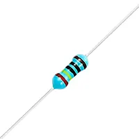
Which components are required?
Voltage regulator IC or transistor, potentiometer, resistors, capacitors, input source.
How do I adjust the output voltage?
By turning the potentiometer or adjusting the resistor network.
Do I need a heatsink?
Yes, for higher current loads to prevent regulator overheating.
Can it supply high current?
Depends on design; linear regulators usually provide 1–2A, switching designs higher.
Is it suitable for beginners?
Yes, simple designs are ideal for hobbyists and electronics students.
Can I add current limiting?
Yes, a resistor or current-limiting circuit can be added.
Can it power microcontrollers and LEDs?
Yes, it is widely used for small electronics projects and testing.
Is it reusable and reliable?
Yes, a well-assembled variable power supply provides long-term stable voltage output.