

Zener Diode Tester
Build a simple Zener diode tester to check Zener voltage and polarity, ensuring proper operation for DIY electronics and hobby projects.

Electronics diode tester:
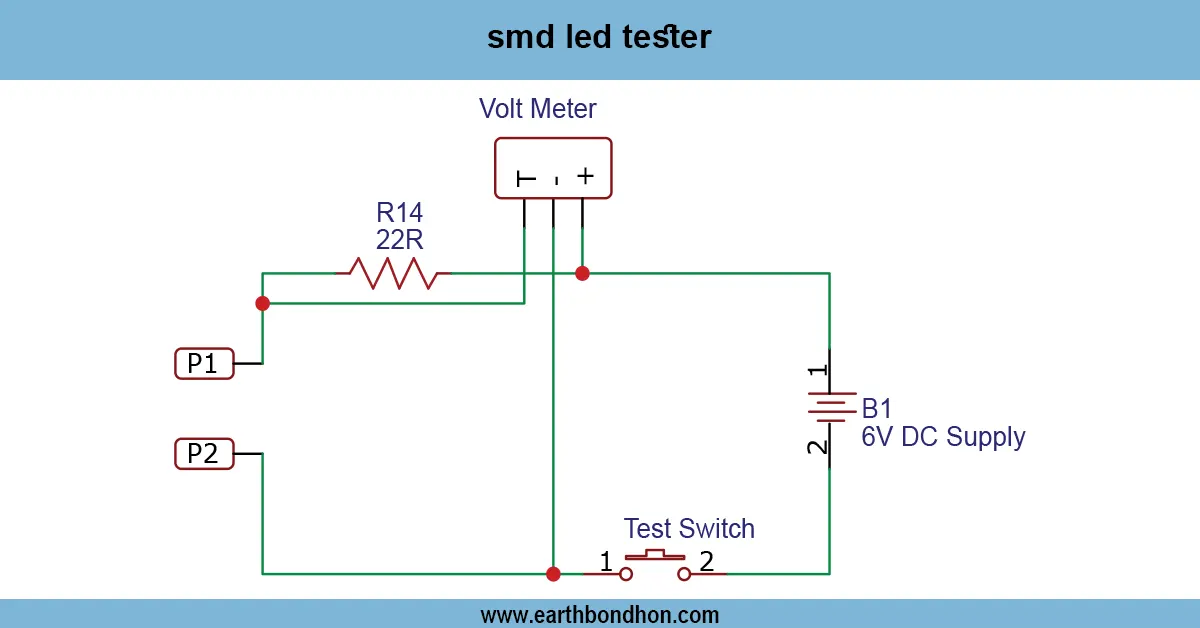
A Zener diode tester is an easy-to-build circuit used to check the Zener voltage and polarity of Zener diodes. It allows electronics enthusiasts and hobbyists to verify that a Zener diode is functioning correctly before using it in circuits. The tester typically uses a series resistor to limit current and a voltmeter or LED indicator to display the Zener voltage. By applying a DC voltage across the diode and observing the voltage drop, the tester confirms whether the diode is operating at its rated breakdown voltage. This simple, low-cost tool is ideal for DIY electronics, labs, and educational purposes.
Zener voltage detection:
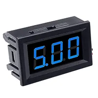
A Zener diode tester is a simple electronic circuit designed to check the functionality, voltage, and polarity of Zener diodes before using them in circuits. It typically consists of a DC power supply, a series current-limiting resistor, and a measurement or indication method, such as a voltmeter or LED. When a Zener diode is connected to the tester, the series resistor limits the current, and the applied voltage allows the diode to conduct at its breakdown voltage. The measured voltage across the diode confirms whether it matches the rated Zener voltage. LED indicators can also provide a visual cue of proper operation. This tester is ideal for hobbyists, DIY electronics enthusiasts, and educational labs to verify components and prevent circuit failures. Compact, low-cost, and easy to assemble, a Zener diode tester ensures accurate voltage regulation and proper diode selection. It is reusable for multiple Zener diodes and helps maintain reliable performance in voltage regulators and electronic projects.
⚡ Work & Installation (Input → Output):
Zener diode testerster works by applying a small DC voltage across the Zener diode through a current-limiting resistor. When the voltage reaches the Zener breakdown voltage, the diode conducts, allowing the tester to measure or indicate the voltage. For visual indication, LEDs can be connected to show proper conduction. To test a diode, connect its anode and cathode to the tester terminals, power the circuit with a suitable DC supply, and observe the voltage across the diode. Ensure the series resistor is appropriately rated to limit current and prevent diode damage. The tester can verify the Zener voltage and check the diode’s polarity, making it useful for selecting the correct component for voltage regulation circuits. Compact and simple to assemble, this tester is reliable and reusable for all Zener diodes within its voltage range.
Testing & Final Adjustments:
After assembling the Zener diode tester, connect a DC power supply within the specified range, typically slightly above the expected Zener voltage. Insert the Zener diode across the tester terminals with correct polarity, ensuring the anode and cathode are connected properly. Use a voltmeter to measure the voltage across the diode. The voltage reading should match the Zener diode’s rated breakdown voltage; if it does, the diode is functioning correctly. If using an LED indicator, it should illuminate when the diode conducts. Adjust the series resistor if the diode receives too much current or the LED is too bright. Test multiple Zener diodes of different voltage ratings to confirm accuracy. Ensure all connections are secure, and avoid exceeding the Zener’s maximum power rating. With proper assembly and testing, the Zener diode testere tester becomes a reliable tool for verifying diode functionality, polarity, and voltage, helping prevent circuit failures in DIY electronics, voltage regulator projects, and educational labs.