Mixer Grinder Wiring Diagram:
This diagram shows how to make a mixer grinder wiring diagram. In this circuit, we use a 3-pin plug, a rotary switch, an indicator lamp, an overload relay, and a universal motor. Here we need to connect all components like our diagram. This circuit is very simple and very easy to make this circuit. If you want to make this circuit and If you want to know more about this circuit please stay with our video below the post.
Advertisements
Diagram of Mixer Grinder Wiring Diagram:

Components needed For this Project:
You can get the components from any of the sites below:
- 3 Pin Plug [See Buy Click Amazon]
- Changeover Switch [See Buy Click Amazon]
- Indicator Light 220v AC [See Buy Click Amazon]
- Overload switch [See Buy Click Amazon]
- single phase Mini Motor[See Buy Click Amazon]
*Please note: These are affiliate links. I may make a commission if you buy the components through these links. I would appreciate your support in this way!
Advertisements
Components used to make the Mixer Grinder Wiring:
01. 3 Pin Top Plug:
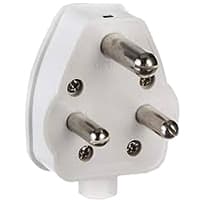
The 3-pin plug tops are used on appliances, extension leads, Light fittings, table fans, etc. The Packaging Comes with Wiring Instructions For the Electrician connection. A transparent cover makes it visually easy to Keep an Eye on the Wiring Connections electrical wire. 3-pin plugs are Designed so That Mains Electricity can be Supplied to Electrical Appliances Safely side. A 3-Pin Plug Consists of 3-pins. Each Pin Must be Correctly Connected to the 3 Wires in the Electrical Cable. Each Wire Has its Own Specified Color so that it can be easily identified power supply.
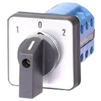
02. Rotary Switch:
Change over switch is a medium of line transfer that is used in industry. Every industry has a supply line using change-over switches to supply power. A Changeover Switch is an Electrical Switch That Allows a load to be Changed from one Electrical Source to Another and vice Versa, Either Manually or Automatically. A Changeover Switch is specially made to transfer a house is electricity from the Normally used Commercial Power supply grid to a more local Generator when a power Outage Occurs.
03. Indicator Lamp:

An indicator lamp just Sounds Technical, Sometimes it is called a Supervisory light Indicator. Indicator lights are amber in color and can be located at the Front, the Rear, and Sometimes at the Side of the car on both the left And Right-hand sides. The Common colors used by Indicator lamps are red, yellow, blue, white, and green line system. A Panel Indicator Lamp Generally has up to 5 Differently Colored Segments to Indicate Various Conditions on the Machine or Process system.
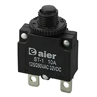
04. Overload Relay:
An overload relay is a safety device that protects your circuit diagram against damage caused by high-power loads. The relay opens if the load exceeds a certain amount. protecting the circuit from destruction. The simplest version of an overload relay is a single-pole, single-throw (SPST) switch. An overload relay is also referred to as a relay switch. switch is a device that opens the circuit in the event of an electrical, thermal, or power overload system. When mounted with a contactor they create a motor starter connection.
05. Universal Motor:
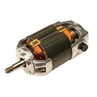
A universal motor is a type of electric motor that can be powered by either AC or DC power and uses an electromagnet as its stator to generate a magnetic field. It is a commutated series wound motor, with the stator field coils connected in series with the rotor windings through a commutator. The universal Motor is structurally very similar to a DC series motor but slightly modified to operate with AC power. This type of electric motor is well operated by AC because the field on both sides can be varied in conjunction with the current flowing through the coil and armature.
Thank You for visiting the website. Keep visiting for more Updates.
Read more Single Phase Wiring
How To Make High Power DC-DC Booster Circuit | Buck-Boost Converter
Introduction content content contentDiagram of Buck-Boost Converter Circuit diagramComponents Needed for this...
DC Motor Control Circuit | Simple DC Motor Speed Controller Circuits
Introduction content content contentDiagram of DC Motor Speed Controller Circuit diagramComponents Needed for...
Battery Low Voltage Protection | over-voltage protection
Introduction content content contentDiagram of Over-voltage Protection Circuit diagramComponents Needed for...
0 Comments