Transformerless Power Supply wiring:
This diagram shows how to make Transformerless Power Supply wiring. In this circuit, we use totals of four diodes, a resistor, and two capacitors. First, we need to connect the diode like in our diagram, then connect the capacitor with diodes and resistors like in our diagram. Now our circuit is ready for use. If you want to know more about this circuit please stay with our video below the post.
Advertisements
Diagram of Transformerless Power Supply wiring:

Components needed For this Project:
You can get the components from any of the sites below:
- 684j (400v) Capacitor [See Buy Click Amazon]
- 10uF (50v) Capacitor [See Buy Click Amazon]
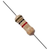
- 1M Ohm Resistor [See Buy Click Amazon]
- 1N4007 Doide [See Buy Click Amazon]
*Please note: These are affiliate links. I may make a commission if you buy the components through these links. I would appreciate your support in this way!
Advertisements
Components used to make the Transformerless Power Supply wiring:
01. Capacitor:
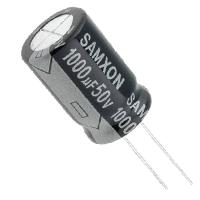
The capacitor is a 2-terminal passive component having the Property of Capacitance. This Property Electrifies (charging with electricity) Capacitors with input Voltage. Capacitor Condense Electricity, Hence it is also known as a Condenser. It consists of 2 Electronic Conductors that are Separated by Distance. The Capacitor Stores Charge and can act like a Battery. It is necessary for filter Circuits to Minimize voltage spikes, and Smoothing changes in voltage.
02. Resistor:
A Resistor is an Electronic component that controls the flow of electricity in an electronic circuit. Or we can say in this way that the material or component That is used to block the flow of current in electronic equipment is called a Resistor. And, because of the characteristic of the resistor or conductor that Prevents the flow of current through the conductor, that characteristic or religion is called resistance, where resistance Means the ability to block. The main function of a resistor is to cause a voltage drop to impede the flow of current in the circuit. In this case, the question may arise as to which circuit or which Parts need to be protected from low voltage or current flow.
03. Diode:

A diode is an Electronic Device that allows current to flow in one direction only current flow. The Diode has two ends. The end where there is a line of silver color is called the cathode. The other end is called the anode. A diode basically allows current to flow in one direction and prevents current from flowing in the opposite direction. Such a tendency of current to flow in one direction is called rectification. When a circuit is connected with an anode positive and a cathode negative it is called a forward bias diode.
Thank You for visiting the website. Keep visiting for more Updates.
Read more Single Phase Wiring
How To Make High Power DC-DC Booster Circuit | Buck-Boost Converter
Introduction content content contentDiagram of Buck-Boost Converter Circuit diagramComponents Needed for this...
DC Motor Control Circuit | Simple DC Motor Speed Controller Circuits
Introduction content content contentDiagram of DC Motor Speed Controller Circuit diagramComponents Needed for...
Battery Low Voltage Protection | over-voltage protection
Introduction content content contentDiagram of Over-voltage Protection Circuit diagramComponents Needed for...
0 Comments