Hair Dryer Wiring Connection:
This diagram shows how to make a Hair dryer Wiring Connection. In this circuit diagram, we use a blower motor, a heating element, 5 diodes, 2 plugs, and a switch. This diagram is very easy to make and connect. If you want to see the connection animation video of this diagram please check our youtube video for more clear information.
Advertisements
Diagram of Hair dryer Wiring Connection:

Components needed For this Project:
You can get the components from any of the sites below:
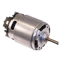
- 775 DC Motor [See Buy Click Amazon]
- 1N4007 Doide [See Buy Click Amazon]
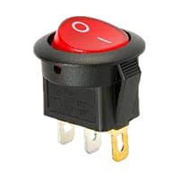
- Rocker Switch [See Buy Click Amazon]
- 2 Pin Plug 220V AC [See Buy Click Amazon]
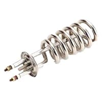
- Heater Element [See Buy Click Amazon]
*Please note: These are affiliate links. I may make a commission if you buy the components through these links. I would appreciate your support in this way!
Advertisements
Components used to make the Hair dryer Wiring Connection:
01. DC Motor:
Direct Current Motors (DC) are Among the Most Commonly Used Electric Motors in a Broad Range of Applications today. Like every Direct Current Motor, they Convert Electric energy into mechanical work. However. DC Motors Differ from other electric motors because they are powered by Direct currents (Direct currents), such as batteries and Direct Currents power supplies. It comprises 2 Essential parts: the stator and the rotor. A Direct Current Motor’s stator is Usually a ring of permanent magnets. Electrical Direct Currents Motors are continuous Actuators that convert Electrical energy into Mechanical Energy.
02. Diode:

A diode is an Electronic Device that allows current to flow in one direction only current flow. The Diode has two ends. The end where there is a line of silver color is called the cathode. The other end is called the anode. A diode basically allows current to flow in one direction and prevents current from flowing in the opposite direction. Such a tendency of current to flow in one direction is called rectification. When a circuit is connected with an anode positive and a cathode negative it is called a forward bias diode.
03. Switch:
Rocker Switches are Used to Turn the Main Power Supplies on Electronic Devices OFF and ON. Rocker Switches House a Button For an Operation That can be Pressed on Either end like a Seesaw To Connect Or Disconnect an Electrical Circuit. The Name "Rocker Switch" Comes From The Rocking Motion That The Switch Makes When The Button is Pressed. They are often used as OFF /ON Switches on the Main Power Supplies for Electronic Devices. Rocker Switches Consist of an operation button, Terminals, Contacts, and Sealing Rubber.
04. 2-Plug:
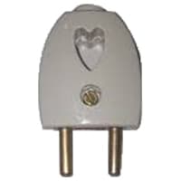
2-Pole Means That the Device Plug is not Earthed and it Normally Has 2-Pins That Transmit Electricity. Originally, all Electrical Devices were Fitted with 2-pole Plugs, Which Means that the Devices were not earthed and that all main Sockets were Constructed for 2-pole plugs system. 2-pin Plugs Consist of 2 flat or Round Pins with one Called “hot” “live” or "line" and the Other Called “neutral”. When Connected to an Electric Circuit, the Current Flows From the live Pins Through The Copper Conductor and into the Device system.
05. Heating Element:
Defrost heaters are used to melt ice formations in refrigeration equipment. They are caused by defrosting water, which freezes inside the lower freezing cold room, collecting in trays or defrost lines. For trays, tubular heaters of various designs are installed. To defrost pipes, wire heaters are wrapped around the pipe. Defrost cable heaters are made in two models, with or without self-regulating elements. A defrost heater is used to help ice conformation in the Refrigerator and is controlled by a Thermostat.
Thank You for visiting the website. Keep visiting for more Updates.
Read more Single Phase Wiring
Basic Electronic MCQ
Basic Electronic Engineering MCQ PDF arranged chapter-wise! Start practicing now for exams, online tests,...
FAQ
Have questions about Electrical, Electronic, or robotics? Find answers here. Frequently asked questions Electrical...
Single phase sdb connection for house wiring
Single phase SDB connection for house wiring: This diagram shows how to make a single-phase SDB connection for house...
0 Comments