DC motor reverse and forward circuit:
This diagram shows how to make a dc motor reverse and forward circuit. In this circuit diagram, we use a DC motor and an SPRT switch, two relays, etc. First, we connect the relays to the SPRT switch exactly like in our diagram. Then connect the motor power from the SPRT switch and relays. Now this circuit is ready for use. If you want to know more details about this diagram, please check our youtube video in the below post.
Advertisements
Diagram of DC motor reverse and forward circuit:

Components needed For this Project:
You can get the components from any of the sites below:
*Please note: These are affiliate links. I may make a commission if you buy the components through these links. I would appreciate your support in this way!
Advertisements
Components used to make the DC motor reverse and forward circuit:
01. 5-Pin Realy:

Relay is a switching device. If current flows through the coil, the coil inside the coil is magnetized and the circuit can be regulated and controlled by on-off switching. Relays are also called protective devices because they close the circuit, component, or device in an emergency to protect it from being burned or damaged. Almost all relays have two source pins and the coil is connected to that source pin. If voltage is applied to this coil then a magnet is created in this coil.
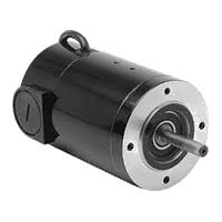
02. DC Motor:
Direct Current Motors (DC) are Among the Most Commonly Used Electric Motors in a Broad Range of Applications today. Like every Direct Current Motor, they Convert Electric energy into mechanical work. However. DC Motors Differ from other electric motors because they are powered by Direct currents (Direct currents), such as batteries and Direct Currents power supplies. It comprises 2 Essential parts: the stator and the rotor. A Direct Current Motor’s stator is Usually a ring of permanent magnets. Electrical Direct Currents Motors are continuous Actuators that convert Electrical energy into Mechanical Energy.
03. SPST Switch:
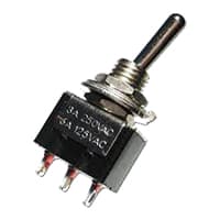
An SPST (Single Pole Single Throw) Switch is a Switch That only Has a Single Input and can Connect Only to one Output. This means it Only Has one Input Terminal and Only 1 Output Terminal. A Switch is a Mechanical or Controlling Device That Changes the Flow of Current Direction or Interrupts the Flow of Current Within a Circuit diagram. An electrical line using Single Pole Single Throws (SPST) is Perfect for on-off switching. When the SPST is closed, the Circuit is Closed and the light from the lamp switches on the system. When The Single Pole Single Throw (SPST) is then opened, the light from the lamp goes out and the Circuit is off.
Thank You for visiting the website. Keep visiting for more Updates.
Read more Single Phase Wiring
Mixer grinder wiring connection
Mixer grinder wiring connection: This diagram shows how to make a mixer grinder wiring connection. In this circuit, we...
Potentiometer wiring for light brightness control
Potentiometer wiring for light brightness control: This diagram shows how to make potentiometer wiring for light...
Temperature sensor fan controller circuit
Temperature sensor fan controller circuit: This diagram shows how to make a Temperature sensor fan controller circuit....
0 Comments