

5 pin relay wiring diagram
Learn the 5-pin relay wiring diagram with terminals 85, 86, 30, 87, and 87a. Step-by-step connection guide for automotive, lighting, and motor control systems.
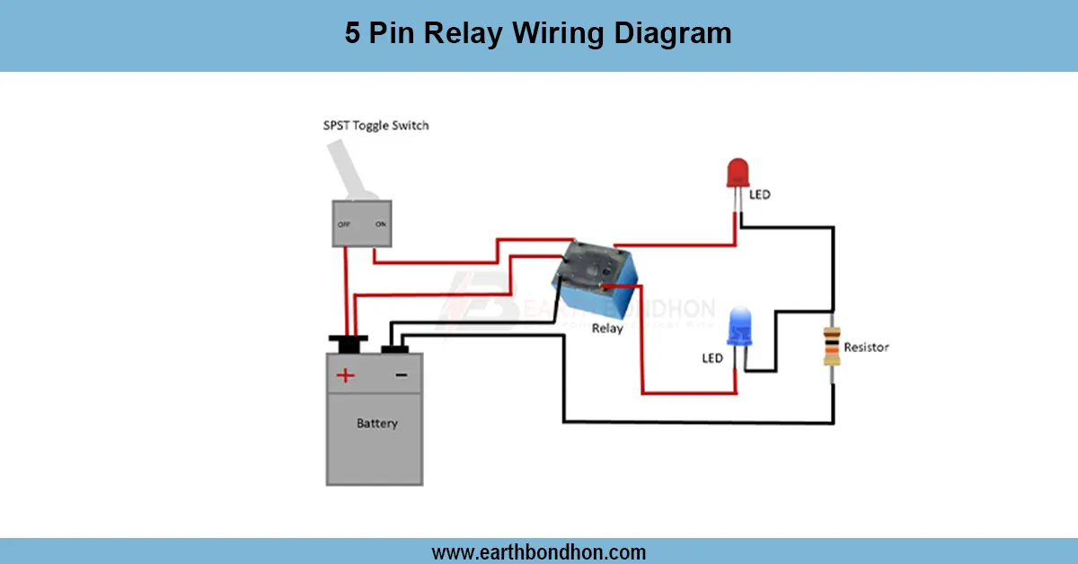
Relay switch wiring diagram
A 5 pin relay has terminals 85 and 86 for coil, 30 as common, 87 as normally open (NO), and 87a as normally closed (NC), allowing dual circuit control.
5 pin relay connection
A 5 pin relay wiring diagram shows the connections for relay terminals 85, 86, 30, 87, and 87a. This relay is commonly used in automotive, lighting, motor, and switching circuits where both normally open (NO) and normally closed (NC) contacts are required.
- Terminal 85 & 86: Coil connections. When energized with 12V or 24V, they create a magnetic field to switch the relay.
- Terminal 30: Common input terminal connected to the power supply.
- Terminal 87: Normally Open (NO) contact, which connects to 30 when the coil is energized.
- Terminal 87a: Normally Closed (NC) contact, which connects to 30 when the coil is de-energized.
This relay allows switching between two circuits or controlling high-current loads with a low-current trigger. For example, in cars, it is used for headlights, horns, fuel pumps, and fan motors.
Work / Installation (Inputs → Outputs)
Input: Battery/Power Supply → Relay Coil (85, 86) → Common Terminal (30).
- Connect terminal 85 to ground/negative.
- Connect terminal 86 to the switch or control signal (positive).
- Connect terminal 30 to the battery positive or common input source.
- Connect terminal 87 to the load that should turn ON when relay is energized.
- Connect terminal 87a to the load that should remain ON when relay is OFF.
Output: When the coil (85–86) is powered, 30 connects to 87 (NO). When coil is OFF, 30 connects to 87a (NC).
Testing & Final Adjustments
After wiring, supply voltage to 85 and 86. Listen for a clicking sound, which indicates the relay is switching. Use a multimeter to check continuity:
- With coil OFF → 30 connects to 87a.
- With coil ON → 30 connects to 87.
Verify proper switching under load. Ensure wires are correctly rated and terminals are tightened. In automotive use, add a fuse between battery and relay input for safety. Label terminals to avoid confusion and prevent wrong wiring. Once tested, the relay provides reliable operation for lights, fans, motors, and automation circuits.