Potentiometer wiring for light brightness control:
This diagram shows how to make potentiometer wiring for light brightness control. This circuit uses a potentiometer, a voltage regulator with a heat sink, 12V Battery, a resistor, and a DC Light. This circuit is very easy and simple to make. This diagram is very simple and very easy to connect. If you want to know more about this circuit please check our youtube video below the post.
Advertisements
Diagram of Potentiometer wiring for light brightness control:

Components needed For this Project:
You can get the components from any of the sites below:
- 10k Ohm Varible Resistor [See Buy Click Amazon]
- 7812 Voltage Regulator [See Buy Click Amazon]
- 10k Ohm Resistor [See Buy Click Amazon]
- 12V Light [See Buy Click Amazon]
*Please note: These are affiliate links. I may make a commission if you buy the components through these links. I would appreciate your support in this way!
Advertisements
Components used to make the Potentiometer wiring for light brightness control:
01. Potentiometer:

This 100K Preset Variable Resistor Potentiometer has Three Terminals and is Mountable on PCB. This Potentiometer is also Easily Usable with Solderless Breadboards. It is Also Known as a Variable Resistor, Viper, pot, or Trimmer. These 100K Preset Variable Resistor Applications are in Various Electronic Devices, Where There is a Need for Changing the Resistance Values on the fly. This 100K Potentiometer Resistor is also Easily Usable with Solderless Breadboards. It is also known as a Variable Resistor, Viper, pot, or Trimmer.
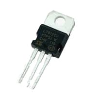
02. Voltage Regulator with Heat Sink:
A Voltage Regulator Allows the Alternator to Make Enough Power to Run the Devices on a Vehicle. However, it only Uses The Power Necessary for the Devices. When a Regulator Fails, The Limits On How Much Power An Alternator Can Produce Disappear. A heat Sink Should be Attached to a Voltage Regulator in Order to dissipate Excess Power that may Enter into The voltage Regulator. This prevents excess Voltage From Destroying and Overheating the Voltage Regulator Since the Heat Sink Dissipates the Excess Power as heat.
03. Resistor:
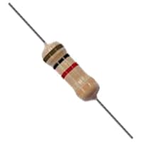
A Resistor is an Electronic component that controls the flow of electricity in an electronic circuit. Or we can say in this way that the material or component That is used to block the flow of current in electronic equipment is called a Resistor. And, because of the characteristic of the resistor or conductor that Prevents the flow of current through the conductor, that characteristic or religion is called resistance, where resistance Means the ability to block. The main function of a resistor is to cause a voltage drop to impede the flow of current in the circuit. In this case, the question may arise as to which circuit or which Parts need to be protected from low voltage or current flow.
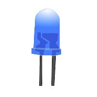
04. LED Light:
Light Emitting Diode (LED) Indicator lamps are a type of LED (Light Emitting Diode) lamp used to Display When a Change Occurs in an Electrical Circuit. When Something has Malfunctioned in an Electrical System, a red or Orange Light light-emitting diode Indicator Lamp may be used to alert a Worker. LED Indicator Lamps Usually consist of a single Bulb. Pilot lights and Light Emitting Diode indicator lights Indicate Lights for Machines or Instruments and they can also be built into Switches. They Provide Solutions for a Variety of Requirements and Are ideal for Highly Reliable Indications.
Thank You for visiting the website. Keep visiting for more Updates.
Read more Single Phase Wiring
How To Make High Power DC-DC Booster Circuit | Buck-Boost Converter
Introduction content content contentDiagram of Buck-Boost Converter Circuit diagramComponents Needed for this...
DC Motor Control Circuit | Simple DC Motor Speed Controller Circuits
Introduction content content contentDiagram of DC Motor Speed Controller Circuit diagramComponents Needed for...
Battery Low Voltage Protection | over-voltage protection
Introduction content content contentDiagram of Over-voltage Protection Circuit diagramComponents Needed for...
0 Comments