AC Motor Speed Controller Diagram:
This diagram shows how to make ac motor speed controller. In this circuit diagram, we use a potentiometer a 2.2k resistor, a DIAC, a TRIAC, a ceramic capacitor, etc. This circuit is very easy to make. First, we need to connect the 100k variable to the 2.2k resistor and DIAC. Then connect TRIAC and ceiramic capacitor. Now this circuit is ready for use. If you want to see this circuit connection video please check out the youtube video below the post.
Advertisements
Diagram of AC Motor Speed Controller Diagram:

Components needed For this Project:
You can get the components from any of the sites below:
- 50k Ohm Varible Resistor [See Buy Click Amazon]
- 2.2k Ohm Resistor [See Buy Click Amazon]
- BB3 Diac [See Buy Click Amazon]
- BT136 TRIAC [See Buy Click Amazon]
- 0.1uF (400V) Capacitor [See Buy Click Amazon]
*Please note: These are affiliate links. I may make a commission if you buy the components through these links. I would appreciate your support in this way!
Advertisements
Components used to make the AC Motor Speed Controller:
01. 100K Potentiometer:

This 100K Preset Variable Resistor Potentiometer has Three Terminals and is Mountable on PCB. This Potentiometer is also Easily Usable with Solderless Breadboards. It is Also Known as a Variable Resistor, Viper, pot, or Trimmer. These 100K Preset Variable Resistor Applications are in Various Electronic Devices, Where There is a Need for Changing the Resistance Values on the fly. This 100K Potentiometer Resistor is also Easily Usable with Solderless Breadboards. It is also known as a Variable Resistor, Viper, pot, or Trimmer.
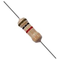
02. 2.2K Resistor:
A Resistor is an Electronic component that controls the flow of electricity in an electronic circuit. Or we can say in this way that the material or component That is used to block the flow of current in electronic equipment is called a Resistor. And, because of the characteristic of the resistor or conductor that Prevents the flow of current through the conductor, that characteristic or religion is called resistance, where resistance Means the ability to block. The main function of a resistor is to cause a voltage drop to impede the flow of current in the circuit. In this case, the question may arise as to which circuit or which Parts need to be protected from low voltage or current flow.
03. DIAC:
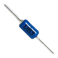
A Diode for Alternating Curren (DIAC) is a Full-Wave or bi-directional Semiconductor Switch That can be Turned on in Both Forward and Reverse Polarities. The name Diode for Alternating Curren comes from the words DIode AC switch. The DIAC (Diode for Alternating Curren) is an Electronics Component that is Widely Used to Assist Even Triggering a TRIAC When used in AC Switches as a result. These Electronic Components are Also Widely used in Starter Circuits for Fluorescent Lamps.
04. TRIAC:
TRIAC Stands for triode for Alternating current. A TRIAC is a Bidirectional, 3-electrode Alternating Current Switch That Allows Electrons to Flow in Either Direction. It is the Equivalent of 2 SCRs Connected in a Reverse-Parallel Arrangement with gates Connected to each Other. A Triode for Alternating Current is Triggered into conduction in both Directions by a Gate signal like That of an SCR. As Suggested by its name, this Electronic Component is Commonly used as a Control Element in AC (Alternating current) circuits. A triode for alternating currents is a Semiconductor Device that Features three Terminals.

05. 0.1uf Ceramic Capacitor:

The capacitor is a 2-terminal passive component having the Property of Capacitance. This Property Electrifies (charging with electricity) Capacitors with input Voltage. Capacitor Condense Electricity, Hence it is also known as a Condenser. It consists of 2 Electronic Conductors that are Separated by Distance. The Capacitor Stores Charge and can act like a Battery. It is necessary for filter Circuits to Minimize voltage spikes, and Smoothing changes in voltage.
Thank You for visiting the website. Keep visiting for more Updates.
Read more Single Phase Wiring
Mixer grinder wiring connection
Mixer grinder wiring connection: This diagram shows how to make a mixer grinder wiring connection. In this circuit, we...
Potentiometer wiring for light brightness control
Potentiometer wiring for light brightness control: This diagram shows how to make potentiometer wiring for light...
Temperature sensor fan controller circuit
Temperature sensor fan controller circuit: This diagram shows how to make a Temperature sensor fan controller circuit....
0 Comments
Trackbacks/Pingbacks