Photo control cell connection wiring:
This diagram shows how to make Photo control cell connection wiring. In this circuit, we use an FP MCB ( Four Pole Minature Circuit Breaker ), a Differential Switch, a magnetic contactor, and a Photocell Sensor. Here we need to connect all components like our circuit diagram and then we can use it in our home and workstation.
Advertisements
Diagram of Photo control cell connection:

Components needed For this Project:
You can get the components from any of the sites below:
- FT MCB 30A [See Buy Click Amazon]
- TP RCCB 20A [See Buy Click Amazon]
- Magnetic Contactor 40A [See Buy Click Amazon]
- Motion Sensor [See Buy Click Amazon]
*Please note: These are affiliate links. I may make a commission if you buy the components through these links. I would appreciate your support in this way!
Advertisements
Components used to make the Photo control cell connection wiring:
01. FP MCB:
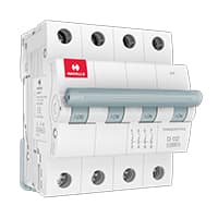
4 pole MCB for 4-Wires Connections, the one additional 4th pole for Neutral Wire Connection so that between Neutral and any of the other three will supply. In 4-Pole MCB the Neutral Pole is also having Protective release as in the Phase Poles connection. 3 Phase Supply with Neutral. TPN means triple pole TP + Neutral which is 3 - phases and Neutral. but the Protection is given for 3 Phases only and in 4 poles MCB Protection is given to all 3-Phases as well as Neutral. In the case of a 4-pole MCB. A Purpose is not to protect the Neutral but it is rather to Isolate the Neutral.
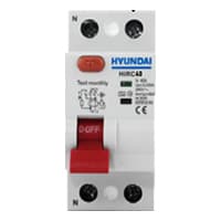
02. Differential Switch:
The Residual Current Circuit breaker RCCB is the Safest device to detect and Trip against Electrical Leakage current. This ensures protection against Electric shock Caused by indirect contact. Circuit breakers (CB) are automatically Operated Electrical Switches that Protect Electrical Circuits from Short-Circuiting or Overloading systems. It Protects against many major accidents. RCCB Circuit Breaker is an Electrical Wiring device whose function is to disconnect the current in the circuit.
03. Magnetic Contactor:

A magnetic contactor is an electromagnetic switching device. It is generally used for controlling 3-phase Motors. The operation of a magnetic contactor is similar to that of a Relay. but a relay is used for low-power or low-voltage connections, and a magnetic contactor is used for high-power or high-voltage connections. As soon as the supply is applied to the magnetic contactor coil. its normally open contacts are closed and normally closed contacts are opened and the associated devices are also operated. This is how a magnetic contactor works.
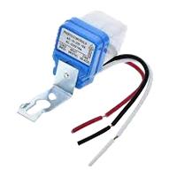
04. Photocell Sensor:
Photocells and Motion Sensors are Electronic Devices you can use to Manage Indoor or Outdoor Lighting. The Main Difference Between Photocells and Motion Sensors is that the Former Detects change in light Levels, and The Latter React to Physical Movement. Movement in the Detection area Changes the Reflected Signals and Activates the Sensor. They also save Energy by Turning Themselves off when Light is Unnecessary. Many Motion Sensors use a Combination of Detection Methods to Provide enhanced Coverage and eliminate false positives. The adjustable timers built into some Sensors let you Control how long the Attached Lights Remain Active after it Detects Motion.
Thank You for visiting the website. Keep visiting for more Updates.
Frequently asked questions
Always connect black wires to black wires and white wires to the white wires. Cover all connections with electrical device tape and tuck all the wires away. Finish installing your light and fixture per the manufacturer's instructions. Once everything is assembled, test your should right as shown above.
The neutral wire is not always required for the basic operation of a photocell switch. However, in some cases, a neutral wire may be needed for specific models or for additional features such as electronic timers or other advanced functionalities.
Check the cable for shorts, nicks, and a ground loop. If the photocell still does not function, measure continuity on the photocell wire (red or blue for a 2-wire photocell or red or blue or green for a three-wire photocell) and check if it is shorted. If a short is found, the photocell was bad and needs to be replaced.
Photocell taps minimize the risk of the transmission that may occur by contact. Water and energy saving: Sometimes we do not take into account the water dripping one by one. In this case, which we find very often in classic taps, the tap continues to spend water constantly dripping.
Another use of battery is that, the electric field of the battery helps us to find the kinetic energy of the electrons which is very important to find the change in the photoelectric effect because it changes with the variation of frequency of light.
Read more Single Phase Wiring
What is a kilowatt-hour (kWh) | kwh formula | What does kwh mean
Introduction to Electrical Units and CircuitskW and kWh on your electricity bill As your home uses electricity during...
What is the Difference Between kVA | What does KVA mean | kVA formula
Difference Between KVA ExplainedWhat does KVA Mean? There are technical terms aplenty when it comes to generators, and...
Power Factor | Power Unit | Energy | Electricity Unit
Power factor definition | Calculating Power FactorPower Factor Values In a purely resistive circuit, the power factor...
0 Comments