Proximity sensor electrical Wiring:
This diagram shows how to make Proximity sensor electrical Wiring. In this circuit, we use a proximity sensor, an 8-pin timer, a magnetic contactor, and a DP MCB ( Double Pole Minature Circuit Breaker ). First, we need to connect the DP MCB with the power source, then connect the contactor with DP MCB, then connect the timer and sensor with the contactor. Now this circuit is ready for use.
Advertisements
Diagram of Proximity sensor electrical Wiring:

Components needed For this Project:
You can get the components from any of the sites below:
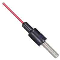
- Proximity Sensor [See Buy Click Amazon]
- 8 Pin Timer 220V AC [See Buy Click Amazon]
- Magnetic Contactor 25A [See Buy Click Amazon]
- DP MCB 25A [See Buy Click Amazon]
*Please note: These are affiliate links. I may make a commission if you buy the components through these links. I would appreciate your support in this way!
Advertisements
Components used to make the Proximity sensor electrical Wiring:
01. Proximity Sensor:
Negative-Positive-Negative (NPN) Proximity Sensors Provide an Active LOW Output. This Means That When an Object Enters the Detecting range of the sensor, the output of the sensor is connected to the ground. This type of sensor is also known as the Sinking sensor. Negative-Positive-Negative and PNP stands for Positive-Negative-Positive Transistors. Negative-Positive-Negative (NPN) Proximity Sensor NPN is Powered on When Enough Current is Supplied From the Transistor base to the Emitter.
02. Timer:
A timer is a type of time-switching device that controls and controls Electrical circuits and electrical and electronic devices through time setting (on/off). The timer is basically 8-pin. Like other controlling devices the timer has a coil and when this coil is magnetized, the timer works on/off. The timer has 2 common ends and each common end has normally close and normally open options. When the timer is set by time, the timer trips at the end of that time and turns the common is normally closed (on) to open (off) and normally open (off) to close (on). This is how the timer works.

03. Magnetic Contactor:

A magnetic contactor is an electromagnetic switching device. It is generally used for controlling 3-phase Motors. The operation of a magnetic contactor is similar to that of a Relay. but a relay is used for low-power or low-voltage connections, and a magnetic contactor is used for high-power or high-voltage connections. As soon as the supply is applied to the magnetic contactor coil. its normally open contacts are closed and normally closed contacts are opened and the associated devices are also operated. This is how a magnetic contactor works.
04. DP MCB:
DP MCB In 2 Pole MCB, switching & protection is affected in phases and the neutral. A Double Pole or DP Switch is a Switch that Controls 2 Circuits at the same time. In terms of Residential Switching, this Normally means it Switches the live and Neutral at the same time. In Layperson Terms, Double Pole switches or DP Switches are Exclusively Designed to Control 2 Different Electrical Circuits at the same time, which allows the Appliances to Isolate safely and reliably. Fan or light Combinations and Medical Equipment are some of the many applications for DP Electrical Switches and Electrical components.

Thank You for visiting the website. Keep visiting for more Updates.
Frequently asked questions
1. Proximity Sensors detect objects without touching them, and they therefore do not cause abrasion or damage to the object. Devices such as limit switches detect an object by, contacting it, Proximity Sensors could detect the presence of the object electrically, without having to touch it.
In a three-wire configuration, two of the three leads supply power while the third switches the load. The term load is identified as the sensor powers. The load could be a lamp, pneumatic valve, relay or machine alarm, PLC input (programmable logic controller) DC input which is the most common type.
A proximity sensor is a sensor that detects the presence of nearby objects without any physical contact. This could be done using the electromagnetic field and electromagnetic radiation beam in which the field or return signal changes in the event of the presence of any object in the surroundings.
It is a 3-wire sensor with an open collector NPN transistor configured in a normally open mode. It requires a power supply of ten to thirty volts DC.
DC units have transistor output and normally have three wires, but NAMUR standard DC sensors have only two wires. Note that units with 2 wires must be connected to their power supply with a load in series, or they should be damaged.
Read more Single Phase Wiring
What is a kilowatt-hour (kWh) | kwh formula | What does kwh mean
Introduction to Electrical Units and CircuitskW and kWh on your electricity bill As your home uses electricity during...
What is the Difference Between kVA | What does KVA mean | kVA formula
Difference Between KVA ExplainedWhat does KVA Mean? There are technical terms aplenty when it comes to generators, and...
Power Factor | Power Unit | Energy | Electricity Unit
Power factor definition | Calculating Power FactorPower Factor Values In a purely resistive circuit, the power factor...
0 Comments