Pump Motor Starter Connection:
This diagram shows how to make Pump Motor Starter Connection. In this circuit, we use a TP MCB ( Tripple Pole Minature Circuit Breaker ), a DP MCB ( Double Pole Minature Circuit Breaker ), a terminal block, a magnetic contactor, an 8-pin relay, a float switch, and a 3-phase motor. First, we need to connect the TP MCB with a power source, then connect the DP MCB with the power source, then connect the terminal block, then connect the contactor, then connect the relay, and float switch with a power source, then connect the 3-phase motor with contactor.
Advertisements
Diagram of Pump Motor Starter Connection:

Components needed For this Project:
You can get the components from any of the sites below:
- DP MCB 16A [See Buy Click Amazon]
- TP MCB 20A [See Buy Click Amazon]
- Terminal Block [See Buy Click Amazon]
- Magnetic Contactor 40A [See Buy Click Amazon]
- 8 Pin Relay (220V AC) [See Buy Click Amazon]
- Float Switch Water Level Controller [See Buy Click Amazon]
- 3 Phase Motor (5 HP) [See Buy Click Amazon]
*Please note: These are affiliate links. I may make a commission if you buy the components through these links. I would appreciate your support in this way!
Advertisements
Components used to make the Pump Motor Starter Connection:
01. DP MCB:

DP MCB In 2 Pole MCB, switching & protection is affected in phases and the neutral. A Double Pole or DP Switch is a Switch that Controls 2 Circuits at the same time. In terms of Residential Switching, this Normally means it Switches the live and Neutral at the same time. In Layperson Terms, Double Pole switches or DP Switches are Exclusively Designed to Control 2 Different Electrical Circuits at the same time, which allows the Appliances to Isolate safely and reliably. Fan or light Combinations and Medical Equipment are some of the many applications for DP Electrical Switches and Electrical components.
02. TP MCB:
The full meaning of MCB is Miniature Circuit Breaker for TP MCB. MCB is an electromagnetic switch or device. If for any reason a short circuit occurs in the supply line or load line (line to line or line to neutral) or in case of overload MCB. the MCB automatically trips and disconnects the main line circuit or household power supply Connection. TP MCB In 3 Pole MCB, Switching & Protection is affected in only 3-Phases and the Neutral is not part of the MCB. 3 pole MCB signifies the Connection of Three Wires for a 3-Phase system Red-Yellow-Blue Phase. 3-Phase Supply Only Without Neutral.

03. Terminal Block:
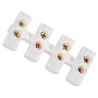
Terminal Clocks are Connectors That Terminate a Single wire and Connect it to a circuit or other system. Terminal Blocks come in a range of shapes, Sizes, and ratings, but Always Terminate a single Wire and are Never multi-pole. Terminal Blocks are used to Secure or Terminate Wires and, in Their Simplest form, Consist of Several Individual Terminals Arranged in a long strip system. Terminals are Useful for Connecting the Wiring to the GND or, in the Case of Electrical power, for Connecting Electrical Switches and Outlets to the Mains side.
04. Magnetic Contactor:
A magnetic contactor is an electromagnetic switching device. It is generally used for controlling 3-phase Motors. The operation of a magnetic contactor is similar to that of a Relay. but a relay is used for low-power or low-voltage connections, and a magnetic contactor is used for high-power or high-voltage connections. As soon as the supply is applied to the magnetic contactor coil. its normally open contacts are closed and normally closed contacts are opened and the associated devices are also operated. This is how a magnetic contactor works.

05. 8-Pin Relay:
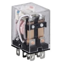
The most popular relay for automation work is the 8 Pin Relay. The 8-pin relay has a DC or AC coil as the main part. which is connected to two pins. There are two common parts. Underneath a Common part are a NO and an NC part. No part is normally open with a common part and the NC part is normally closed. The timer base used for automation is the same as the 8-relay base. That is, switching can be done using the timer base. This is basically how a relay switch works for the relay.
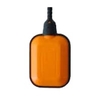
06. Float Switch:
A Float Switch is a type of Level Sensor Device Used to Detect the level of liquid within a tank. The Switch May be Used to Control a Pump, as an Alarm, as an Indicator, or to Control Other Devices. 1 type of Float Switch Uses a Mercury Switch Inside a Hinged float. Another common type is a Float Switch That Raises a rod to Actuate a Microswitch. One Pattern Uses a reed Switch Mounted in a Tube Float, Containing a Magnet, Surrounding the Tube, and Guided by it.
07. 3 Phase Motor:

A 3-phase electric motor uses a 3-phase Power Supply to Convert Electric Energy into Mechanical Energy. It contains four Wires (Three hot Wires and one Neutral Wire) and Uses 3 Alternating Currents of the Same Frequency. Since it Generates a Rotating Magnetic Field, it does not need a Capacitor for the Startup. Some 3-phase Motors are Reversible, Which Means they can serve as Generators by Turning Mechanical Energy into Electrical Energy.
Thank You for visiting the website. Keep visiting for more Updates.
Frequently asked questions
Submersible pump starters are your safeguard, or a submersible starting pump panel keeps your water supply from short-circuiting. They serve both functions by avoiding overloading or short-circuiting. It is simple to do with a simple on-and-off switch operation.
The author has 958 answers and 4.9M answer views on Apr 8. A single-phase motor starter is a device used to start and control the operation of a single-phase electric motor. It typically consists of a contactor, an overload relay, or various control components.
Examine the circuit diagram breaker and the fuses to the submersible pump to ensure that they are operating correctly. Replace blown fuses or reset the breaker if it has been tripped. With the submersible pump pressure of the switch in a closed position, check the voltage across the switch.
A pump failure is a mechanical and electrical problem that prevents a pump from functioning correctly. This could be caused by various issues, including a broken impeller, a loss of power supply, or a clogged filter.
Replace the plug, clean the plug prongs with abrasive paper, and have the electrical receptacle replaced. The branch circuit diagram is wiring too small to carry the pump load. Have the line voltage checked or compare it with the manufacturer's specifications. The pump should be plugged into its own circuit diagram breaker (or fuse).
Read more Single Phase Wiring
What is a kilowatt-hour (kWh) | kwh formula | What does kwh mean
Introduction to Electrical Units and CircuitskW and kWh on your electricity bill As your home uses electricity during...
What is the Difference Between kVA | What does KVA mean | kVA formula
Difference Between KVA ExplainedWhat does KVA Mean? There are technical terms aplenty when it comes to generators, and...
Power Factor | Power Unit | Energy | Electricity Unit
Power factor definition | Calculating Power FactorPower Factor Values In a purely resistive circuit, the power factor...
0 Comments