Single line diagram of power system:
This Diagram shows Single line diagram of the power system. This circuit diagram is very simple and easy to make. If you want to know more details about this circuit please check our youtube video below the post. Please stay with our website for more updates about electrical electronics and robotics projects gadgets and circuits.
Advertisements
Diagram of Single line diagram of power system:

Components needed For this Project:
You can get the components from any of the sites below:
- Single Phase Generator 2000W[See Buy Click Amazon]
- 3 Phase Transformer [See Buy Click Amazon]
- Busbar wire [See Buy Click Amazon]
- 3 Phase Motor (5 HP) [See Buy Click Amazon]
*Please note: These are affiliate links. I may make a commission if you buy the components through these links. I would appreciate your support in this way!
Advertisements
Components used to make the Single line diagram of power system:
01. Power Generator:
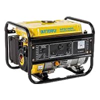
An electric generator is a type of Electrical device that converts mechanical energy or power into electrical energy or power. However, dynamo generally refers to generators only. The first generator built was called a dynamo. This electrical device makes this conversion using the principle of kinetic electromagnetic energy generation. According to Farad is principle of electromagnetic induction, a dynamic electromagnetic induction is induced in a conductor when it passes through a magnetic flux.
02. Transformer:
The Primary Winding of the 3-Phase Transformer is Energized from a 3-Phase Supply. The Flux is Produced in the Core by the Primary Currents in the 3 Windings. The core has Three Limbs, where any 2 limbs act as a return path for the Flux in the Third limb. A 3-phase, 50Hz Transformer has a Delta-Connected Primary and Star-Connected Secondary, the line Voltages being 22,000V and 400V Respectively. The secondary has a Star-Connected Balanced load at 0.8 Power Factor Lagging for 3-phase line system. 3-phase has 4 Wires, Three actives called phases, and one neutral.
03. Busbar:
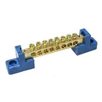
A busbar is a type of Electrical conductor. It is made of copper brass or aluminum. Busbar is most commonly used in factories. We supply the power from the transformer to the busbar. We take the electricity from this busbar to the circuit breaker. The advantage of using a busbar is that through it we can provide multiple power connections in multiple places very easily. How many thick copper bars are aggregates of busbars? A copper bar is rectangular (rectangular) copper type or triangular in shape.
04. 3-Phase Motor:
A 3-phase electric motor uses a 3-phase Power Supply to Convert Electric Energy into Mechanical Energy. It contains four Wires (Three hot Wires and one Neutral Wire) and Uses 3 Alternating Currents of the Same Frequency. Since it Generates a Rotating Magnetic Field, it does not need a Capacitor for the Startup. Some 3-phase Motors are Reversible, Which Means they can serve as Generators by Turning Mechanical Energy into Electrical Energy.

Thank You for visiting the website. Keep visiting for more Updates.
Frequently asked questions
In a single-line electrical diagram, each transmission or distribution power supply line appears as a single line on the page, rather than as three (or four) lines showing individual conductors in a 3-phase AC circuit diagram. This condenses the space or complexity of the diagram for simpler troubleshooting.
From the electrical engineering and safety aspect, electrical SLD was the main resource for calculating short-circuit diagram currents, determining selective protection coordination, or ultimately calculating incident energy – making it one of the most important of the safety documents available at the facility.
What is a single-line diagram. The single-line diagram was a graphical representation of an electrical installation. It differs from other diagrams because, in the case of the Single Line diagram, each circuit diagram was represented by a single line, in which all the conductors of the corresponding section are represented.
In electrical engineering, a single-phase electric power supply (abbreviated 1φ) is the distribution of alternating current flow electric power using a system in which all the voltages of the power supply vary in unison. Single-phase distribution is used when loads are mostly lighting and heating, with a few large electric motors.
A diagnosis was made through a combination of observation, interviews, family history, and school reports. Neuropsychological testing may be used to help find the best to help the individual with a specific learning disorder.
Read more Single Phase Wiring
What is a kilowatt-hour (kWh) | kwh formula | What does kwh mean
Introduction to Electrical Units and CircuitskW and kWh on your electricity bill As your home uses electricity during...
What is the Difference Between kVA | What does KVA mean | kVA formula
Difference Between KVA ExplainedWhat does KVA Mean? There are technical terms aplenty when it comes to generators, and...
Power Factor | Power Unit | Energy | Electricity Unit
Power factor definition | Calculating Power FactorPower Factor Values In a purely resistive circuit, the power factor...
0 Comments